USER INTERFACE
PAGE 8
REV. 02 2012-MAY-18
CHECKFIRE MP-N Electric
Detection and Actuation System Manual
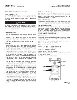
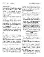
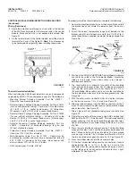
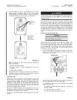
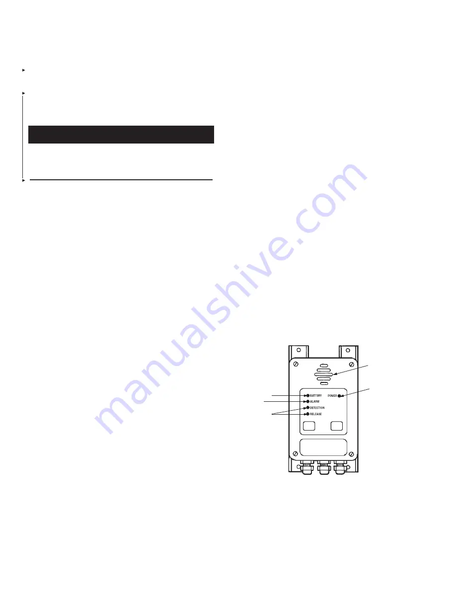
SOUNDER
GREEN
YELLOW
RED
YELLOW
FRONT PANEL INDICATORS
(See Figure 17)
Battery Trouble
(Yellow)
The yellow BATTERY LED will pulse once every 10 seconds when
the internal battery has reached its low-power threshold. Refer to
Installation Section (page 19) for proper battery replacement
procedure.
Battery must be replaced when yellow BATTERY LED is flash-
ing. Failure to replace battery will prevent the CHECKFIRE
module from activating a discharge. If a fire occurs, there could
be personal injury and/or property damage.
Power Normal
(Green)
• LED pulses once every 3 seconds when indicating normal
power
• The green Power Normal LED pulses “on” once every 3
seconds indicating power is normal. If the power drops below an
acceptable level, the green Power LED will be extinguished.
Also, the Yellow Battery LED will pulse, indicating trouble.
Alarm
(Red)
• The alarm LED will flash if an alarm condition exists. An alarm
condition is caused by operation of the detection circuit or oper-
ation of the manual pull/pressure switch input circuit. The alarm
condition will continue until the source of the alarm is removed
and the control module is reset.
DETECTION CIRCUIT NO. 1 ACTIVATION MODE – Upon
receipt of an input to the detection circuit, the Alarm LED and
the sounder will pulse at a rate of 2 times per second and will
continue at this rate until the first time delay period has expired.
After the first time delay, a second time delay mode is initiated.
This causes the LED and sounder to pulse at a rate of 4 times
per second.
After discharge, the LED and sounder will continue to pulse at
a rate of 4 times per second for 30 seconds. After that, it will
switch to the trouble mode and pulse once every 10 seconds.
INITIATING INPUT CIRCUIT NO. 2 – When programmed to
cause a release, the first time delay mode will be by-passed and
the LED will pulse at a rate of 4 pulses per second while the
second time delay runs through its timing cycle. After the time
delay setting is reached, it will pulse another 30 seconds at the
same rate. After that, the control module will go into the post-
discharge mode, at which time the Alarm LED and Release LED
will pulse at a rate of one pulse per 10 seconds.
PRESSURE SWITCH CIRCUIT (FEED BACK) – When pro
-
grammed as a pressure switch circuit, the Alarm LED will pulse
a minimum of 30 seconds at 4 pulses per second. The control
module will then go into the post-discharge mode and the Alarm
and Release LED will pulse at a rate of one pulse per 10
seconds.
Detection Trouble
(Yellow)
The Yellow Detection Trouble LED and the audio pulse once every
10 seconds when the control module detects a trouble in the
detection circuit. The control module will automatically return to
normal when the trouble is cleared.
Release Trouble
(Yellow)
The Yellow Release LED and the audio will pulse at a rate of once
every 10 seconds when a trouble condition is detected in the
release circuit. The control module will return to normal when the
trouble condition is cleared.
The Release trouble will also pulse after the system has
completed a discharge cycle or a pressure switch feed back signal
has been received. The trouble signal in this condition is used to
indicate a recharge of the fire suppression system is necessary. A
Release trouble under either of these conditions can only be
cleared by resetting the control module.
Sounder
(Audio)
The sounder gives the audio indication for all alarm and trouble
outputs. The sounder will pulse at the same rate as the visual
corresponding LED.
The sounder gives the audio indications of the various outputs.
The sounder is rated at 85 Db at 10 feet.
The pulse rates are as follows:
Alarm – Time Delay 1 = 2 pulses per second
Time Delay 2 = 4 pulses per second
Trouble – 1 pulse per 10 seconds
Loss of Power – 1 pulse per 10 seconds
Release Circuit Fired – 4 pulses per second for 30 seconds, then
1 pulse per 10 seconds
Low Battery – 1 pulse per 10 seconds
FIGURE 17
002760
!
CAUTION


