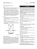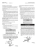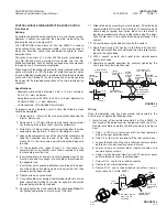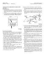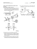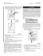
FRONT PANEL BUTTONS
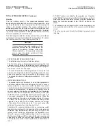
(See Figure 18)
Delay
• Pushing the “DELAY” button during the first time delay cycle will
restart the time delay cycle. If the second time delay cycle has
already started, the “DELAY” button will have no effect.
• The “DELAY” button can also be used to check the diagnostics
function. By depressing the delay button when the system is in
the trouble condition, the LEDʼs will flash a pattern code. Each
pattern code indicates a certain type of trouble. The code
pattern is prioritized. The first trouble must be fixed before
addressing the next one. Once the first trouble is taken care of,
depressing the “DELAY” button will cause the LEDʼs to indicate
the code for the next trouble, if there is one. When the “DELAY”
button is pressed, three short audio and visual indications will
acknowledge the switch has been depressed properly.
Reset
• The “RESET” button is used to re-initialize the control panel.
When depressed, it provides an indication that all LEDʼs and the
sounder are functional.
• It is used to upload the manual programming into the control
module.
• If trouble(s) has not been cleared, the trouble indication will
reappear after the RESET button is pressed.
• When the “RESET” button is pressed, three short audio and
visual indications will acknowledge the switch has been
depressed properly.
FIGURE 18
0002760
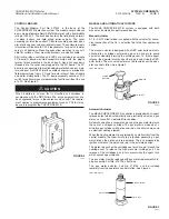
BATTERY CONNECTION
The 3.6 VDC internal lithium battery is connected to the control
module by a removable type plug. The battery is supplied with two
separate plug-in connectors. One connector is used for plugging
into MP-N modules and the other connector is used for plugging
into SC-N modules. CAUTION: Do not cut off unused connector
assembly. It must remain on battery module even though it is not
used. Simply tuck the extra connector assembly along side the
battery module when installing the cover.The battery must be
replaced annually or when the Yellow Battery LED and sounder
are pulsing. A label is attached near the battery mounting location
for recording the installation date.
Discharged lithium batteries may contain significant amounts of
unused energy and should be handled with care. Do not
compact for disposal. Before disposal, each battery must be fully
discharged and electrically isolated by enclosing in a plastic bag
and sealing the bag. Do not dispose of in fire. Check applicable
solid waste disposal regulations for proper disposal of more than
one battery.
BATTERY REPLACEMENT
• While in use, the battery requires replacement every year or
when the Yellow Battery LED and sounder are pulsing. The
battery must be replaced only by an authorized ANSUL service
representative.
• The battery is held in place by a battery strap requiring a special
tool for removal
• The shelf life of the battery is 8 years
• Control Module contains a label for recording battery replace-
ment date
• Refer to Installation Section for battery replacement procedure
(page 19), New Battery Installation
• Make certain used battery is disposed of properly
ENCLOSURE
• The enclosure is watertight. It meets the requirements of
International Standard IEC 529, “Degrees of Protection
Provided by Enclosures” for an IP 66 rating
COVER REMOVAL
• The cover is attached with four tamper-proof screws
• When removing and installing cover, make certain seal is always
correctly in place and not twisted
• Seal should always be kept clean
• A small amount of silicone lubricant will improve the seals effec-
tiveness.
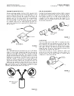
STRAIN RELIEF INSTALLATION
• Always use Dow Corning 737 RTV Sealant or equal on all strain
relief and plug male threads
MOUNTING
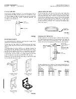
There are four types of mounting options available for the
CHECKFIRE MP-N Control Module.
• Control Module can be mounted without a bracket. It has
molded-in mounting tabs on the back box. Note: Surface must
be suitable.
• Control Module can be mounted on a combined bracket which
will allow both the module and the manual actuator to be
mounted together.
• Control Module can be mounted on its own bracket and the
manual actuator can be also mounted on its own bracket.
• Control Module can be mounted to an existing CHECKFIRE MP
bracket by the use of a retrofit bracket.
The Control Module should never be mounted in an area
which is subject to pressure washing or steam cleaning.
!
CAUTION
USER INTERFACE
2012-MAY-18 REV. 02 PAGE 9
CHECKFIRE MP-N Electric
Detection and Actuation System Manual
RESET
BUTTON
RESET
DELAY
DELAY
BUTTON


