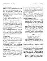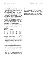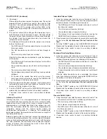
CONTROL MODULE WIRING/DETECTION WIRE ROUTING
(Continued)
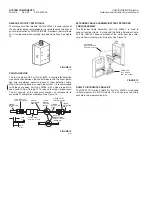
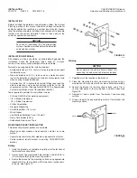
Splicing
If possible, the detection wire should be run in a continuous piece.
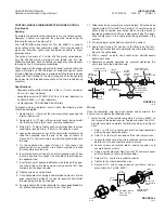
However, if splices are required, they must be made using the
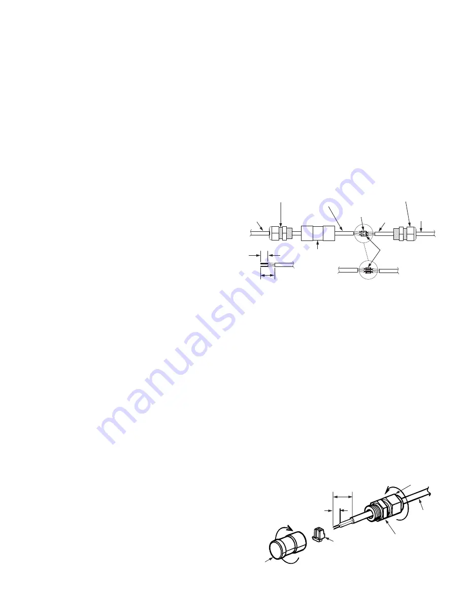
following technique. See Figure 26.
The CHECKFIRE In-line Splice Kit, Part No. 428375, is used to
make splices of the linear detection cable. It can also be used to
make the transition splice from non-detection cable to linear
detection cable.
The splice kit consists of Part No. 426783 plastic splice bodies,
Part No. 423546 plastic water-tight strain reliefs, and Part No.
433284 splice block. Each kit contains enough of each component
to make up ten (10) complete assemblies.
When used with the proper size smooth round jacketed cable, the
splice will provide an IEC IP68 level of protection against water
intrusion. Additional protection is provided by filling the splice body
cavity with Dow Corning 737 sealant (or equal), and also applying
the sealant to the threaded connections of the strain reliefs during
assembly.
Specifications:
• Allowable cable outside diameter: 0.08 in. (2 mm) minimum,
0.24 in. (6.1 mm) maximum
• Acceptable wire size: 22 AWG (0.0253 in. (0.6 mm) diameter) to
18 AWG (0.0403 in. (1 mm) diameter)
• UL Recognized, CSA Certified Strain Reliefs
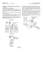
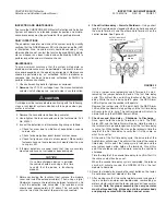
To properly make a detection circuit splice, the following steps
should be completed:
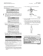
1. Remove 3/4 in. (19 mm) of the wire outer jacket, exposing the
internal Mylar wrap.
2. Remove 3/4 in. (19 mm) of the wire mylar wrap, being careful
not to damage the internal heat sensitive conductors.
3. Strip 3/8 in. (10 mm) of heat sensitive insulation from the inner
conductors, leaving 3/8 in. (10 mm) of insulation on each.
4. Loosen the compression nut of the strain relief assembly and
slide the assembly over the end of the wire as shown in
Figure 26. On the same wire end, slide the splice body onto
the wire.
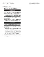
5. On the opposite wire, repeat Steps 1-3, then loosen the
compression nut on another strain relief assembly and slide
that assembly onto the wire.
6. Insert splice block on end of one set of exposed wires. Wires
must be inserted far enough into slice block to protrude out
the opposite side.
7. Insert other set of exposed detection wire through the oppo-
site side of the splice block, again making certain that they
protrude out the opposite side.
8. Tighten screws on splice block.
9. Once splice block assembly is completed on both sets of wire
ends, apply Dow Corning 737 sealant (or equal) to strain relief
threads going into the splice body.
10. Securely tighten the strain relief into the splice body.
Note:
Do
not tighten compression nut unto wire at this time.
11. Slide splice body assembly near splice block. Fill splice body
approximately 3/4 full with Dow Corning 737 sealant and pull
splice body assembly over splice block so slice block is
located approximately half way inside splice body. This oper-
ation should result in the splice block being enclosed in the
sealant.
12. Fill remainder of splice body cavity with the sealant.
13. Apply Dow Corning 737 sealant to the thread on the unat-
tached strain relief lock nut and thread this strain relief assem-
bly unto the splice body.
14. With a wrench on both strain relief locks, simultaneously
tighten both ends.
15. Complete assembly operation by securely tightening the
strain relief onto the detection wire.
FIGURE 26
007045
Wiring
Once the detection wire has been routed and secured in the
hazard area, complete the following steps:
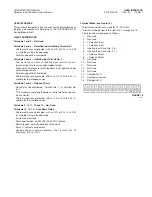
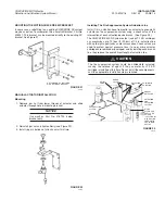
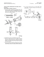
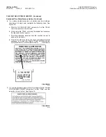
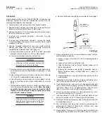
1. Install an end of line resistor assembly, Part No. 426520, to
the far end of the detection wire. To properly attach the E.O.L.
Resistor assembly, complete the following steps (see Figure
26a):
a. Strip 1 in. (25 mm) of outer jacket off the linear detection
wire or the spot detection cable.
b. Strip 1/4 in. (6 mm) of insulation off the two inernal wires.
c. Loosen the lock nut on the strain relief connector and slide
both lock nut and connector over end of wire.
d. Loosen screws on terminal block, insert bare wires, and
securely tighten screws.
e. Apply a small amount of Dow Corning 737 sealant or equal
on male threads of strain relief connector.
f. Screw E.O.L. cap to strain relief connector.
g. Tighten lock nut onto detection wire.
h. Secure E.O.L. cap to support device (by others) using a
nylon cable tie, Part No. 56991.
FIGURE 26a
002774
INSTALLATION
2012-MAY-18 REV. 02 PAGE 15
CHECKFIRE MP-N Electric
Detection and Actuation System Manual
LINEAR
DETECTION
WIRE
STRAIN RELIEF,
PART NO. 423546
SPLICE
BLOCK,
PART NO.
433284
OVERLAP
CONDUCTORS
UNDER SCREW
TERMINALS
LINEAR
DETECTION
WIRE
LINEAR
DETECTION
WIRE
LINEAR
DETECTION
WIRE
STRAIN RELIEF,
PART NO. 423546
SPLICE BODY,
PART NO. 426783
3/4 IN.
(19 mm)
3/8 IN.
(10 mm)
TERMINAL BLOCK
WITH 4.7 OHM
RESISTOR
STRAIN RELIEF
CONNECTOR
1/4 IN.
(6 mm)
INSTALLED
DETECTION
WIRE
LOCK
NUT
E.O.L.
CAP
1 IN.
(25 mm)


