CONTROL MODULE WIRING/DETECTION WIRE ROUTING
(Continued)
Thermal Detector Installation (Continued)
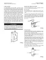
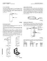
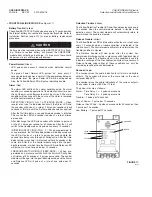
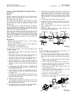
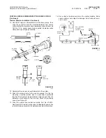
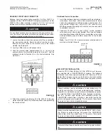
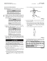
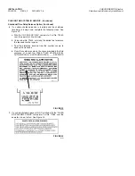
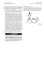
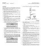
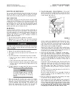
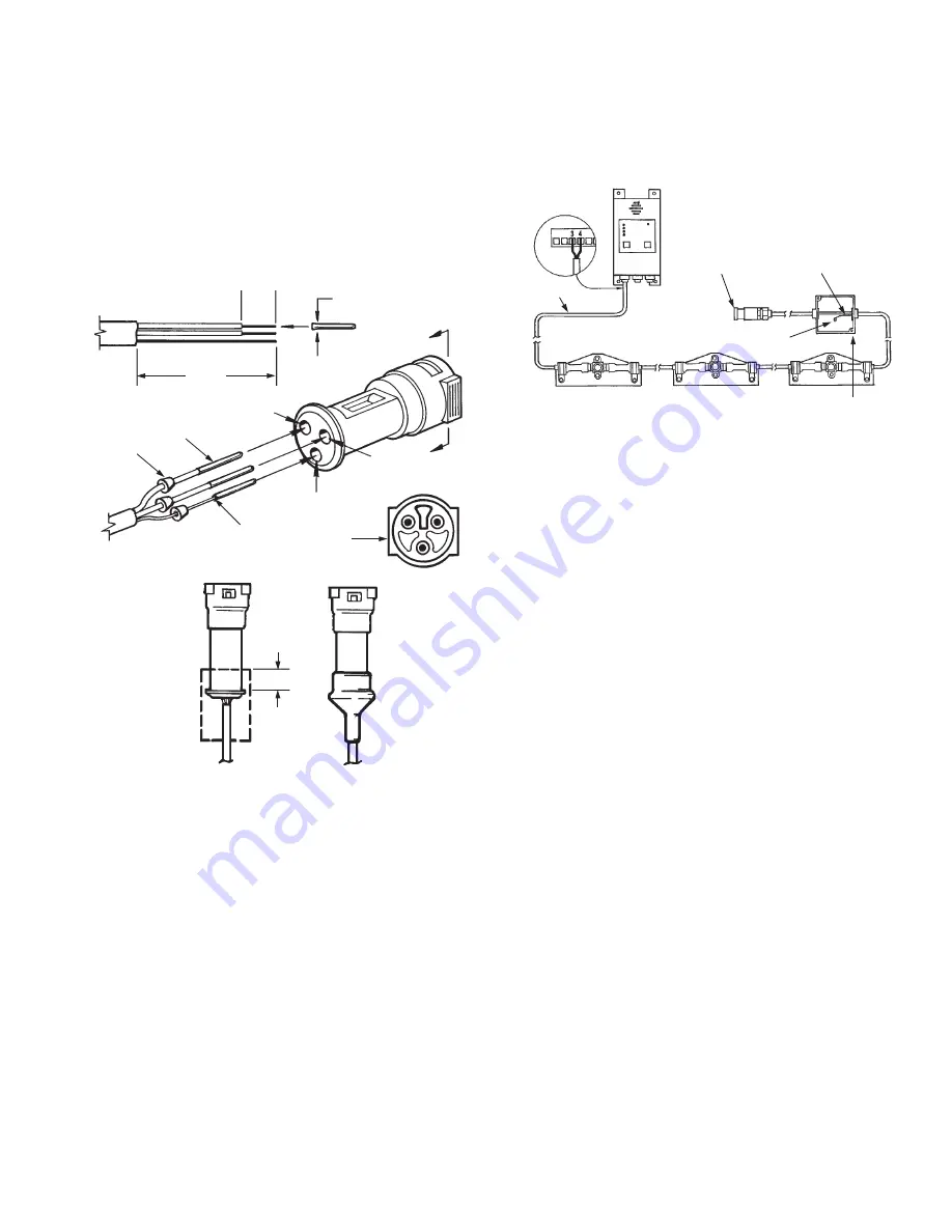
12. Coat the O-ring(s) on the detector(s) with silicon grease, then
snap the connector onto the mounted detector and secure
cable to detector bracket using appropriate cable clamp and
1/4-20 x 1/2 in. socket head screw supplied in detector cable
clamp package shipping assembly.
FIGURE 29
000876
13. Complete this process on each detector in the system.
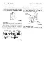
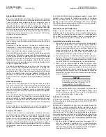
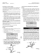
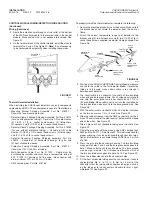
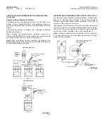
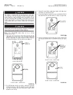
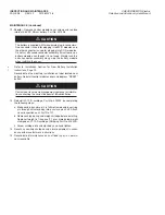
14. Attach the ground wire to the vehicle ground. Do this by
mounting a sealed junction box in a convenient, protected
location. The box must be mounted to a rigid support. Run the
detection circuit cable to the box and attach to grounding
screw. See Figure 30.
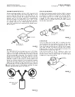
15. Attach the end-of-line resistor assembly, Part No. 426520.
See Figure 30. See instruction sheet included with end-of-line
resistor shipping assembly for detailed assembly information.
16. Run cable to the terminal strip at the control module. Make
certain cable is not subject to damage. Install cable to termi-
nals 3 and 4.
FIGURE 30
002766
INSTALLATION
2012-MAY-18 REV. 02 PAGE 17
CHECKFIRE MP-N Electric
Detection and Actuation System Manual
GROUND SCREW
GROUND
WIRE
JUNCTION BOX
DETECTION
CIRCUIT
E.O.L. RESISTOR
ASSEMBLY,
PART NO. 426520
CRIMP
POSITION
SHRINK
TUBING
AFTER
HEAT
TREATING
3/8 – 1/2 IN.
(9 – 13 mm)
VIEW AA
RUBBER
SLEEVES
PINS
GROUND
WIRE
A
2
3
1 (GROUND)
A
1 1/4 IN.
(32 mm)
1/4 IN.
(6 mm)

