INSPECTION AND MAINTENANCE
To ensure the CHECKFIRE MP-N Electric Detection and Actu a tion
System will operate as intended, proper inspection and mainte-
nance procedures must be performed at the specified intervals.
DAILY INSPECTIONS
The equipment operator must check the system daily by visually
verifying that the GREEN power LED is flashing and no other LED
is illuminated. Also, no audio alarm should be sounding. If any
other conditions exist, contact the local authorized ANSUL distrib-
utor or whoever has been trained and authorized by ANSUL to
perform inspection and maintenance checks.
MAINTENANCE
To give maximum assurance that the system will operate as
intended, maintenance must be performed at six-month intervals
or sooner depending on the operating environment. Maintenance
should be performed by an authorized ANSUL distributor or
someone who has been trained and authorized by ANSUL to
perform maintenance checks.
1. Check all mounting bolts for tightness or corrosion.
2.
Remove
the LT-10-R cartridge from the manual/automatic
actuator, install shipping cap, and set aside in a safe location.
Cartridge must be removed before continuing with the following
steps or accidental system actuation will take place when gas
motor is actuated.
3. Remove the connector lead from the gas motor.
4. Hand tighten the lead connector onto the test module, Part
No. 423541.
5. Inspect the detection and interconnecting wiring as follows:
a. Check for wear due to vibration at penetrations, around
corners, etc.
b. Check for damage from direct impact or other abuse.
c. Check for tightness at points of securement. Make certain
fasteners have not come loose which would allow the wire
to sag or shift.
6. If thermal detectors are used, check that they are securely
mounted and have not corroded or been damaged.
NOTICE
If a vehicle shutdown device is installed,
the vehicle should be running at this time
to verify that the device is functioning
properly.
7. Before conducting the functional test, remove the module
cover and install the extender cable(s). Then, using a digital
Ohmmeter, measure the resistance between terminals 3 and
4 with the detection wire connected. The resistance value
should read approximately 4.7K ohms. This will verify the
circuit is intact and the end-of-line resistor is connected.
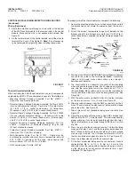
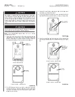
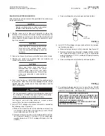
8.
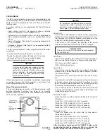
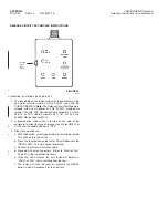
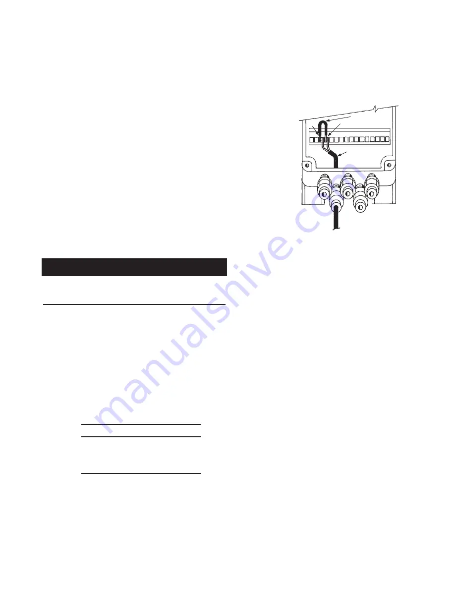
Check first time delay – Alarm to Shutdown
– Using a short
length of insulated wire stripped at both ends, hold one end of
the wire to Terminal 3 and the other end to Terminal 4 on the
control module. See Figure 43.
FIGURE 43
002770
Using a jumper wire, temporarily short Terminals 3 and 4,
removing the jumper before the end of the first time delay
cycle. This will test the non-latching function of the first time
delay. While the wire is being held in place, the RED Alarm
LED will pulse and the sounder will operate.
Remove the jumper wire. At this point, both the RED Alarm
LED and the sounder will stop pulsing and the first time delay
will recycle back to zero. The control module will return to
normal with only the GREEN Power LED on.
9.
Check second time delay – Shutdown to Discharge
–
Once again, hold the wire on Terminals 3 and 4. The RED
Alarm LED and the Audio Alarm will pulse. Hold the wire on
the terminals for a period longer than what the first time delay
is set up for. While holding the wire on the terminals, time the
length of the first time delay to verify that it is the same as
what it was set for.
At the end of the first time delay cycle, the pulse rate of the
Audio Alarm will change. This will start the cycle of the second
time delay. At this point, the timing cycle is latched, and the
wire jumper need not be held on the terminals. Also at this
point, the shutdown relay will operate, causing the vehicle to
shutdown.
Time the length of the second time delay to confirm that it is
the same as what has been set.
When the second time delay cycle is completed, the release
circuit will activate causing the GREEN LED on the test
module to illuminate.
10. Reset test module by pressing the reset button on the tester.
Do not disconnect test module at this time.
11. After making sure that the control module is reset and operat-
ing in a normal non-alarm non-trouble mode, remove the gas
motor actuator cable from the tester and connect to gas motor
assembly.
Note: For proper assembly, the new gas motor
must be threaded fully, 6 threads, onto the actuator body
and properly secured with the allen head set screw.
!
CAUTION
INSPECTION AND MAINTENANCE
2012-MAY-18 REV. 02 PAGE 27
CHECKFIRE MP-N Electric
Detection and Actuation System Manual
DETECTION CIRCUIT
TERMINALS 3 AND 4
4
DETECTION
CIRCUIT
WIRING
JUMPER
3

