TROUBLESHOOTING
2012-MAY-18 REV. 02 PAGE 29
CHECKFIRE MP-N Electric
Detection and Actuation System Manual
DIAGNOSTICS
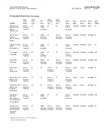
The diagnostics feature offers a means to pinpoint various trouble
symptoms by displaying a flashing code on the control module
status LEDʼs.
If there is more than one trouble at a time, the system will display
them in a pre-set priority.
In multiple trouble situations, the first trouble must be cleared
before the system will display the next one.
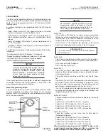
The system must be in the trouble mode in order to display the
diagnostics codes.
With the system in the trouble mode, depress the “DELAY” button.
With the “DELAY” button depressed, the trouble codes will be indi-
cated on the LEDʼs.
LED Code
Trouble
_________
_______
Yellow Battery LED flashing
Internal battery requires
replacement
Yellow Release LED flashing
Release circuit is open
Yellow Release LED flashing
Release circuit has operated
Red Alarm LED flashing
Yellow Detection LED flashing
Detection circuit is open
Yellow Detection LED flashing
Initiating input circuit No. 2
Red Alarm LED flashing
is open
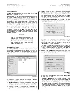
HISTORY BUFFER
The CHECKFIRE MP-N control module is programmed to record
faults, alarms, and programming changes in a numerical
sequence. The module will store approximately 55 recorded
events (when software v4.11 is installed). If the number of events
exceeds 55, the earlier events will be erased to make room for the
later ones.
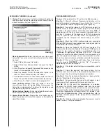
A sample History Buffer screen appears as follows:
Event
dddd:hh:mm:ss
Description
0
0000:00:00:32
Programmed
1
0000:00:01:46
Detection TD1 Initiated
2
0000:00:01:52
Delay Engaged
3
0000:00:02:15
Delay Released
4
0000:00:02:25
Detection TD2 Initiated
5
0000:00:02:35
Release Initiated
6
0000:00:05:10
Manual Reset
7
0000:00:05:13
All Clear
8
385:12:24:32
Internal Battery Low
9
405:20:32:07
Internal Battery Fault
The recorded event indicates which circuit had a fault or an alarm
recorded. Along with the type of fault or alarm, the history buffer
also records the time, relative to the last time the module was
powered up. New events are recorded by days: hours: minutes:
seconds that have transpired from the last time the module was
powered up. If power is removed and then restored, the counter
starts over at 0000:00:00:00; however, previous history will remain
until deleted manually.
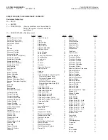
Below is a listing and explanation of each type of recorded history
event:
All Clear:
The module is free of any fault or alarm conditions.
Amp-Hours Limit Exceeded*:
Indicates that the charge drawn
off the battery has exceeded the recommended limit. The battery
must be serviced immediately. (Ver. 4.11 only)
Amp-Hours Reset*:
Charge accumulator has been successfully
reset to zero. (Ver. 4.11 only)
Bad Checksum:
Indicates that an error has been detected in the
E-Prom. If this occurs, the factory default program settings are
restored.
Delay Engaged:
Indicates the delay button has been depressed
during TD1 of an alarm condition.
Delay Released:
Indicates the time the Delay button was
released after initiating.
Detection Circuit Fault:
Indicates an open circuit in the detec-
tion circuit.
Detection TD1 Initiated:
Indicates the Time Delay 1 sequence
has been initiated. This occurs as a result of operation of the
detection circuit.
Detection TD2 Initiated:
Indicates the start of the Time Delay 2
sequence as a result of a detection input.
Int Bad Log:
Indicates an error has been detected in the datalog.
If this occurs, the datalog is automatically cleared and reset.
Internal Battery Fault:
Indicates that the internal battery voltage
has dropped below the minimum operating threshold or the
battery has been disconnected.
Internal Battery Low:
Indicates the internal battery voltage has
dropped below a “Normal” threshold level and requires replace-
ment.
Manual Fault:
Indicates an open in initiating input circuit No. 2 or
pressure switch circuit.
Manual Reset:
Indicates the Reset button has been depressed.
The clock is not reset during a soft reset.
Manual Time Delay:
Indicates the start of the time delay as a
result of the initiating input No. 2 input circuit being initiated.
Pressure Switch:
Indicates activation of the pressure switch
input circuit.
Programmed:
Indicates the unit is programmed or a program-
ming change has been made using the PC programming option.
Release Circuit Fault:
Indicates an open in the gas motor circuit
or the gas motor has fired.
Release Initiated:
Indicates the control module has fired the gas
motor.
Switch Enabled:
Indicates the manual programming switch is
enabled and the program settings are being taken from the
program switch settings.
Unknown:
Indicates an unexplainable event in the control
module circuitry.
* Software V4.11 only

