TOTAL SYSTEM DESCRIPTION (Continued)
Circuits
The first initiating circuit is the supervised detection circuit
designed to be connected to linear (wire), linear pneumatic, and/or
spot type thermal detectors that provide a contact closure input to
initiate a fire detected condition. The second initiating circuit is
designed to accept a contact closure type of actuating device such
as an electric manual pull station or a pressure switch. The initiat-
ing circuits are low impedance and designed to eliminate nuisance
alarms associated with contact bounce.
Two field programmable time delays provide timing of shutdown
and release functions associated with the operation of the detec-
tion initiating circuit No. 1 and initiating circuit No. 2.
NOTICE
If factory preset time delay periods are to be
extended, consider the lag time between fire
ignition and automatic initiation when using
thermal detection. Consequently, extending
one or more time delay periods will likely
extend the fire burn time.
• DETECTION INITIATING CIRCUIT NO. 1
The detection circuit consists of two time delays:
The first time delay is field programmed to assign the time
between alarm (initiation of the detection circuit) and the opera-
tion of the shutdown relay. The first time delay is field program-
mable for 5, 10, 20, or 30 seconds.
The second time delay is field programmed to assign the time
between the completion of the first time delay (when the shut-
down relay operates) and the operation of the release circuit.
The second time delay is field programmable for 0, 10, 20, or 30
seconds.
• INITIATING CIRCUIT NO. 2
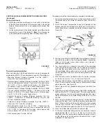
The second input circuit (terminals 5 and 6) is field programma-
ble to be used as either an initiating input circuit to cause a
release output or as a pressure switch feedback input circuit
which will sound alarms and transfer the shutdown relay, but will
not cause a release output. If selected as an initiating circuit to
cause a release, its operation will override the first time delay
function and initiate a second time delay condition, causing the
shutdown relay to immediately operate and system release to
occur upon completion of the second time delay. When the
second input circuit is used as an initiating input circuit to cause
a release, the timing cycle of the second time delay can be
adjusted in steps from 0 to 30 seconds. However, the settings
of time delay 2 on initiating circuit No. 2 can never exceed the
settings of time delay 2 on initiating circuit No. 1.
Selection of the second initiating circuit as a pressure switch
feedback circuit will result in the operation of the alarm relay and
shutdown relay immediately upon receiving the signal. The
release circuit will not be initiated from this feedback circuit.
When the pressure switch feedback input circuit has operated,
the Alarm and Release LEDʼs, along with the audio sounder, will
pulse for 30 seconds at a fast rate and thereafter at a slow rate
until the pressure switch is reset and then the control module is
reset.
• A “DELAY” option is available for the operators use. Operation
of the “DELAY” button will restart the first time delay cycle if initi-
ated while the first time delay is active. Once the second time
delay has started, operation of the “DELAY” button has no
affect.
• The shutdown relay will operate after the first time delay cycle
or immediately upon actuation of the pressure switch feedback
circuit.
This relay can be used for vehicle shutdown or remote alarm
initiating.
TOTAL SYSTEM DESCRIPTION
PAGE 2
REV. 02 2012-MAY-18
CHECKFIRE MP-N Electric
Detection and Actuation System Manual


