background image

44

EN

4  SYSTEM DESCRIPTION

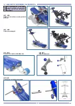
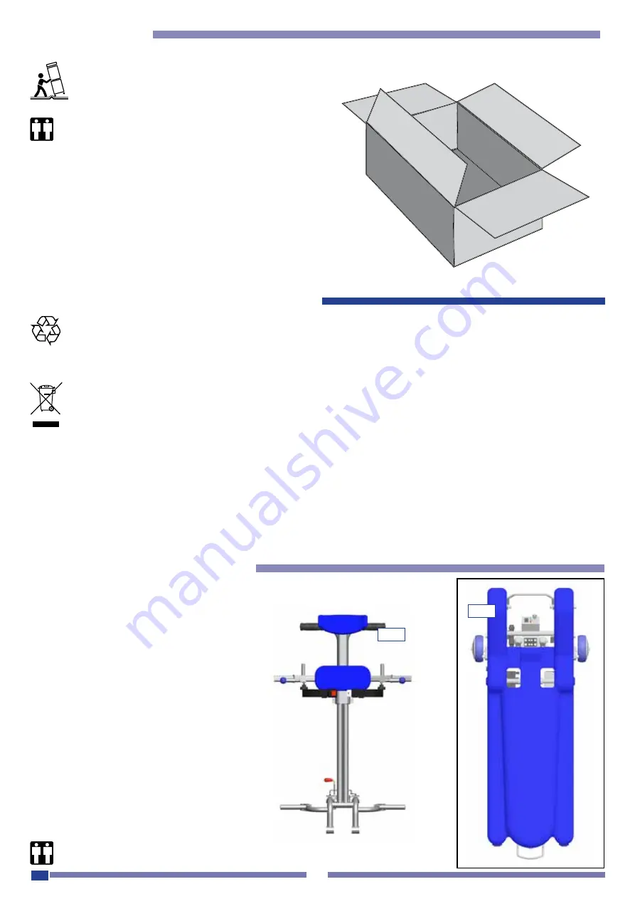
The LG2004 stair chairs allow transporting

a wheelchair with a disable passenger 2

on the stairs of a building due to a particular

electromechanical  system  capable  of  cros-

sing 1

steps.

The movement is continuous and performed 

by the operator using the control push buttons 

on the handlebar.

2

1

Pursuant to Art. 13 of Directive 2002/96/EC on waste electrical and electronic equipment,.

The symbol of the crossed-out wheeled bin on a machine or its packaging indicates that at the end of the product’s 

life it must be collected separately from other waste.

The separate collection of this equipment that has reached the end of its useful life is organized and handled by the 

manufacturer. Therefore users who wish to dispose of this equipment must contact the manufacturer and follow the 

system that the manufacturer has adopted for the separate collection of the equipment that has reached the end of its life. 

Proper separate collection for the subsequent recycling, treatment and disposal of the disused equipment in a manner com-

patible with the environment helps avoid possible negative effects on health and the environment and contributes to the reuse 

and/or recycling of the materials used to make the equipment. Illegal dumping or other improper disposal of the product by its 

owner shall result in the application of the penalties provided for by the laws and regulations in force.

For further more detailed information about treatment, recovery and recycling of this product, please contact the appropriate 

local office about the law in force.

•  Open the package and remove its content taking care 

not to damage it.

3.1  Environmental protection recommendations

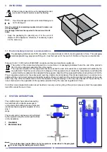
The packaging materials are 100% recyclable.  For proper disposal, refer to local regulations in force.  The packaging 

materials (plastic bag, polystyrene filling, etc.) must be kept out of the reach of children as they are a potential risk. 

3 UNPACKING

When a trolley is used to move the packaged product, 

use caution to avoid injuries caused by tipping.

Once the product is completely unpacked, check to make sure 

it is not damaged.  

Any damage noted must be reported to the carrier within 24 

hours.

•  Keep  the  packaging  for  possibly  use  it  in  the  event  of 

shipment of the appliance; otherwise, if necessary, repack 

it in the same way. 

1  Handlebar

2  Motorized base

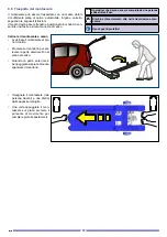
The motorised base can be lifted only by two persons, as described in the paragraph 

8.9 concerning the loading of a motor vehicle

Summary of Contents for LG2004

Page 1: ...IT EN Rel 7_160715 Uso e manutenzione Use and maintenance handbook TRACKS MOBILE STAIRWAY CLIMBER MONTASCALE A CINGOLI LG2004 LG2004 150 LG2004 180 LG2004 150 A008 ...

Page 2: ......

Page 3: ...teristiche scale 19 7 USO PREVISTO DAL COSTRUTTORE 20 8 USO DELL AUSILIO 21 8 1 Carica della batteria 21 8 2 Verifica pendenza delle scale 22 8 3 Uso quotidiano 23 8 4 Spostamento della base motorizzata 23 8 5 Aggancio della carrozzina 23 8 6 Conduzione su scale 24 8 7 Salire le scale 26 8 8 Scendere le scale 28 8 9 Trasporto del montascale 30 9 MANUTENZIONE ORDINARIA 31 Tabella della manutenzione...

Page 4: ...vimento si notano danneggiamenti causati dal trasporto l apparecchio non deve essere utilizzato occorre contattare il servizio di assistenza tecnica per una verifica e revisione del mezzo stesso Il dispositivo deve essere utilizzato da persone in grado fisicamente di controllare la massa dell apparecchio o della persona trasportata Il conduttore del dispositivo deve aver preso completa co noscenza...

Page 5: ... sempre a monte rispetto al mezzo il montascale quindi non deve essere impiegato in modo diverso ad esempio con il conduttore a valle ove si creerebbe un alto pericolo per il conduttore per il trasportato e per la macchina stessa La carrozzina Le regolazioni e le impostazioni del montascale sono deter minate dalla costruzione della carrozzina Durante la fase di certificazione del conduttore verrà ...

Page 6: ...to dalle frecce TV2104 0200 TV2104 0210 Divieto di indossare scarpe con tacchi o ciabatte Indossare solo scarpe chiuse In caso di sosta sulle scale Per assicurare la massima stabilità è opportuno se possibile ar restare il mezzo quando la parte anteriore dei cingoli è in presa sul gradino inferiore e comunque quando sono in presa il maggior numero di scalini Rimuovete sempre la chiave del quadro q...

Page 7: ...levare con cautela il timone per posizionare il montascale in posizione di discesa Al termine della salita Arrestate la marcia e poi tirate il manubrio per posizionare il montascale in piano PUNTO DI EQUILIBRIO PUNTO DI EQUILIBRIO Divieto di indossare scarpe con tacchi o ciabatte PUNTO DI EQUILIBRIO PUNTO DI EQUILIBRIO Indica il punto in cui le masse sono in equlibrio Attenzione pericolo Leggere i...

Page 8: ... smaltimento abusivo del prodotto da parte del detentore comporta l applicazione delle sanzioni amministrative previste dalla normativa vigente Aprite l imballo e estraete il suo contenuto con cau tela ponendo attenzione a non danneggiarlo 3 1 Consigli sulla salvaguardia dell ambiente Il materiale di imballo è riciclabile al 100 Per lo smaltimento seguite le normative locali Il materiale di imball...

Page 9: ...nubrio 15 Manopola regolazione poggiatesta 16 Pomello regolazione poggiaaschiena e agganci 17 Connettore del carica batteria 18 Ruote di manovra 19 Cingoli in gomma 20 Quadro con chiave 21 Maniglia posteriore 22 Sicurezza inferiore aggancio manubrio 23 Maniglia anteriore 24 Indicazione punto di equilibrio delle masse 25 Appoggio ruote carrozzina 26 Sgancio inferiore manubrio 1 2 25 5 6 4 3 9 7 8 1...

Page 10: ...ella 32 Albero di aggancio 30 10 11 12 31 32 18 19 Il pulsante di emergenza 11 deve essere utilizza to solo in particolari condizioni di avaria ovvero quando il sistema di trazione dovesse rimanere in moto anche rilasciando i pulsanti di SALITA e DISCESA ...

Page 11: ...sizione 0 OFF nessuna funzione elettrica è abilitata 2 Indicatore di carica della batteria vedi capitolo carica batterie 3 Pulsante marcia avanti e indietro ausilio 1 3 2 33 Contatti elettrici lato manubrio 34 Contatti elettrici lato base motorizzata 35 Cinture di sicurezza 33 35 34 ...

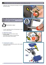
Page 12: ...ione alta abbassate la leva di sicurezza S e poi abbassate completamente il manubrio fino al suo innesto 5 1 Montaggio del manubrio M S A Clic Il dispositivo viene fornito smontato in due parti corpo mac china motorizzato e manubrio Queste operazioni devono essere compiute esclusivamente da personale qualificato o centro di assistenza Attenzione Non tentate di innestare il manubrio sull albero pos...

Page 13: ... essere utilizzata solo quando la leva superiore S è inefficace a causa di qualche problema durante il regolare funzionamento utilizzate solamente la leva superiore S 5 2 Smontaggio del manubrio M S S L S1 S Se la leva di sicurezza S non è posizionata correttamente il funzionamento del montascale è disabilitato Le leve di sicurezza S superiore e S1 inferiore sono col legate fra di loro tramite una...

Page 14: ...e a causa di qualche problema durante il regolare funzionamento utilizzate solamente la leva superiore L Queste operazioni devono essere compiute esclusivamente da personale qualificato o centro di assistenza L La carrozzina deve essere quella verificata e accettata dal tecnico incaricato dall azienda produttrice del montascale Le leve di sblocco L superiore e L1 inferiore sono colle gate fra di l...

Page 15: ...lla carrozzi na fino a quando la traversa T sarà a contatto dei manici della carrozzina Spostate il sistema fino a quando avvertirete uno scatto scatto di sicuro bloccaggio In unione all altezza dovrete regolare i bloccaggi della carrozzina portando le piastre P a contatto con il telaio schienale della carrozzina Di conseguenza i perni Q si troveranno all interno del telaio Ciascun manico della ca...

Page 16: ...dalla carrozzina Allentate la manopola U per regolare l altezza del poggia testa e quindi serrate la manopola 5 5 Regolazione poggiatesta La carrozzina è bloccata U 5 4 Sgancio carrozzina B Queste operazioni devono essere compiute esclusivamente da personale qualificato o centro di assistenza Fra la posizione di apertura e chiusura è stata studiata una posizione di sicurezza che l utente può trova...

Page 17: ...15 IT 5 6 Installazione delle pedane e regolazioni per LG2004 150 A008 Queste operazioni devono essere compiute esclusivamente da personale qualificato o centro di assistenza 1 2 3 4 ...

Page 18: ...16 IT Queste operazioni devono essere compiute esclusivamente da personale qualificato o centro di assistenza 5 6 OK NO 60cm 3 0 c m 7 ...

Page 19: ...17 IT Queste operazioni devono essere compiute esclusivamente da personale qualificato o centro di assistenza 8 9 10 Clic 11 12 ...

Page 20: ...18 IT 13 14 Clic Queste operazioni devono essere compiute esclusivamente da personale qualificato o centro di assistenza ...

Page 21: ...one del carica batteria 100 240 V 50 60 Hz 100 240 V 50 60 Hz 100 240 V 50 60 Hz 100 240 V 50 60 Hz Autonomia della batteria piani rif persona di 80kg 27 27 27 27 Autonomia della batteria piani rif persona di 130kg 22 18 18 12 Autonomia con indicatore carica in riserva piani 4 4 4 4 Tempo medio di carica della batteria ore 8 8 8 8 Temperatura di immagazzinaggio con imballo in ambiente asciutto 10 ...

Page 22: ...ssere utilizzato da persone conduttori che non abbiano preso completa visione delle norme dettate nel presente manuale Non può essere utilizzato da conducenti aventi una struttura fisica esile o comunque non in grado di controllare la massa totale Non può essere utilizzato in ambienti soggetti a spruzzi di acqua o a condizioni atmosferiche critiche o sfavorevoli Non deve essere inoltre utilizzato ...

Page 23: ...e il fusibile è integro occorre verificare il caricabat terie ed eventualmente provvedere alla sostituzione delle batterie stesse vedi cap Manutenzione Le batterie sono rifiuti speciali pertanto possono essere smaltite solo tramite ditte specializzate Prima dell uso quotidiano del dispositivo verificare sempre lo stato e l efficienza generale dell ausilio e la carica delle batterie Se il dispositi...

Page 24: ...ro a bolla Affrontate la scala senza passeggero e senza carrozzina per verificare la corretta pendenza tramite l inclinometro Quando tutto il cingolo è sulla scala occorre controllare l incli nometro e seguire scrupolosamente le successive istruzioni 100 cm 35 max 70 cm max Bolla fra il verde e il rosso inclinazione circa 35 Queste operazioni devono essere compiute esclusivamente da personale qual...

Page 25: ... è responsabile della chiave Premete il pulsante SOLLEVAMENTO L in modo da manovrare il montascale agevolmente sul pavimento Aprite gli appoggi delle ruote Posizionate il montascale sotto la carrozzina e quindi premete uno dei pulsanti AVANTI o INDIETRO per riposizionare automaticamente il montascale a contatto col pavimento e quindi in posizione stabile La base motorizzata può essere spostata anc...

Page 26: ...cale Leggere il manuale d istruzione Rischio schiacciamento dita nella trasmissione mec canica Indossare solo scarpe chiuse La persona che conduce il mezzo su scale sia in salita che in discesa deve essere in possesso di una abilitazione che vie ne concessa dall azienda produttrice o da un suo mandatario autorizzato solo dopo che questa persona ha acquisito una diretta istruzione teorico pratica e...

Page 27: ...ulsante per arrestare il mezzo Riavvio dopo un arresto di emergenza Una volta eliminata la causa che ha indotto il conduttore ad azio nare il pulsante di emergenza sbloccate il pulsante ruotando la testa nel senso indicato dalle frecce stampate sul pulsante stesso Guasto al sistema motore principale In presenza di un guasto che rende inattivo il montascale durante il suo uso sulle scale occorre No...

Page 28: ...emendo il pulsante INDIETRO Il motore fa arretrare il montascale mentre il pulsante rimane premuto b Condotto a mano dopo aver premuto il pulsante di solleva mento In prossimità delle scale occorre premere il pulsante IN DIETRO per abbassare i cingoli a pavimento mantenendo saldamente impugnato il manu brio premete il pulsante di salita INDIETRO il montascale salirà verso di voi in modo lineare e ...

Page 29: ...ano Le scale sono terminate Ponete la chiave del quadro in posizione O OFF e sfilatela per assicurarsi che nessuno se non il conduttore abilitato possa utilizzare il dispositivo Potete ora liberare la carrozzina S4 Il montascale viene tirato verso il con duttore S5 Il montascale viene azionato indietro verso il conduttore ...

Page 30: ... STOP PUNTO DI EQUILIBRIO Conducete in modo dritto il montascale verso la scala e fate sporgere con gradualità l ausilio fino a quando il Punto di equilibrio indicato sulla base si troverà all incirca sullo spigolo del gradino Arrestate il montascale sul punto di equilibrio Tenendo saldamente impugnato il manubrio rilasciate il montascale che ruoterà verso la scala siete pronti per la discesa CICL...

Page 31: ...o Potete ora liberare la carrozzina Discesa Premete il pulsante di discesa AVANTI il montascale scenderà davanti a voi in modo lineare e costante In qualsiasi momento rilasciando il pulsante il montascale si ferma Continuate a scendere fin quando raggiungerete il piano D4 Il montascale è in fase di discesa D5 Il montascale è in contatto con il piano D6 Il montascale è sul piano ...

Page 32: ...tascale al pia no di carico Premete sul manubrio per sol levare la parte anteriore fino al piano di carico Quando la parte anteriore è ben poggiata sul piano di carico sganciate il manubrio Impugnate il montascale una persona davanti e una dietro dalle apposite maniglie Una volta appoggiato il mon tascale sul piano premete il pulsante di movimento per compiere piccoli spostamenti Operazioni che de...

Page 33: ... delle ruote rif 9 3 In funzione dell uso e della necessità procedere alla pulizia delle parti indicate Pulizia dei cingoli rif 9 4 In funzione dell uso e della necessità procedere alla pulizia delle parti indicate 1 anno Controllo generale controllo della funzionalità delle ruote controllo usura cingoli controllo del sistema frenante controllo dell integrità della tappezzeria e delle imbottiture ...

Page 34: ...ente l ausilio su un lato in modo che il ma nubrio poggi sul pavimento in questo modo potete accedere alla parte inferiore Rimuovete il materiale e la sporcizia che può essersi incuneata o appic cicata ai cingoli In concomitanza con questa opera zione controllate anche lo stato di usura dei taccoletti dei due cingoli Se trovate dei danneggiamenti come parti di taccoletti mancanti o usura oltre il ...

Page 35: ...ta Il fusibile da 60A è bruciato ponete la chiave in I ON sbloccate il pulsante di emergenza controllare bene l innesto rimuovere il manubrio e pulire i contatti verificare e inserire bene sostituire il fusibile SIstema di sollevamento I comandi non vengono accettati La chiave non è in posizione ON Il pulsante di emergenza è premuto Il manubrio non e correttamente inserito I contatti del manubrio ...

Page 36: ...ento controllo usura ruote di sollevamento controllo usura leve di sicurezza controllo efficienza batteria controllo dispositivi ancoraggio carrozzina controllo integrità telaio e timone controllo indicatore di pendenza controllo sistema cingoli e puleggia controllo trasmissione meccanica controllo ancoraggio poggiatesta controllo cinture di sicurezza controllo contatti elettrici manubrio corpo ma...

Page 37: ...posteriori ø300 mm ART A007 Pattini per passeggini Per l installazione e l uso degli aggiuntivi riferitevi alle istruzioni accluse alla fornitura dell aggiun tivo stesso ART A009 Sistema di sicurezza antiribaltamento ART A010 Prolunga per carrozzina maggiorata ART A023 Attacchi universali ...

Page 38: ... Timbro e firma del centro di assistenza Data MANUTENZIONE PROGRAMMATA 72 mesi Timbro e firma del centro di assistenza Data MANUTENZIONE PROGRAMMATA 36 mesi Timbro e firma del centro di assistenza Data MANUTENZIONE PROGRAMMATA 60 mesi Timbro e firma del centro di assistenza Data MANUTENZIONE PROGRAMMATA 84 mesi Timbro e firma del centro di assistenza Data MANUTENZIONE PROGRAMMATA 84 mesi Timbro e ...

Page 39: ... intervento Timbro e firma del centro di assistenza Data Descrizione intervento Timbro e firma del centro di assistenza Data Descrizione intervento Timbro e firma del centro di assistenza Data Descrizione intervento Timbro e firma del centro di assistenza Data Descrizione intervento Timbro e firma del centro di assistenza Data ...

Page 40: ... non autorizzato le spese di trasporto e imballaggio per eventuali spedizioni del prodotto in garanzia sono a carico del cliente La garanzia non dà in nessun caso diritto a risarcimento di danni I pezzi di ricambio sono disponibili per 10 anni Nel caso in cui il cliente rileva problematiche al prodotto dovrà informare immediatamente il produttore o il suo mandatario nel proprio paese fornendo indi...

Page 41: ... Characteristics of staircase 57 7 MANUFACTURER S INTENDED USE 58 8 USING THE DEVICE 59 8 1 Charging the battery 59 8 2 Stairs sloping control 60 8 3 Everyday use 61 8 4 Moving the motorised base 61 8 5 Hooking the wheelchair 61 8 6 Handling on stairs 62 8 7 To go up stairs 64 8 8 To go down stairs 66 8 9 Transport of stair chairs 68 9 ROUTINE MAINTENANCE 69 Routine maintenance table 69 9 1 Cleani...

Page 42: ...ll safety mechanisms are working properly The manufacturer ANTANO GROUP SRL Via Todi 15 Zona Industriale Torre Matigge 06039 TREVI PG declares and guarantees under its sole responsibility that the mobile stair climber with tracks to transport per sons with impairments on wheelchair code LG 2004 mobile stairclimber Cod Iso 18 30 12 003 medical device of class I as from classification established by...

Page 43: ... board in order to gain the maximum safety and handiness particularly during the operations of going up and down the stairs The operator must always be on board machine so the stair chairs must not be used in a different way for example when the operator is down otherwise the operator the person being transported and the machine may be in danger Wheelchair The adjustments and settings of the stair...

Page 44: ...ion may be reset by turning the button head in the direc tion indicated by the arrows TV2104 0200 TV2104 0210 Do not wear shoes with heels or slippers Only wear closed shoes During stop on stairs To ensure the maximum stability if possible stop the vehicle when the front of tracks cover the lower step and anyway the most of steps Always remove the key from the control panel when the stair chairs a...

Page 45: ...wn Carefully lift the wheel to position the stair chairs downward At the end of the climb Stop the running and then pull the handlebar to position the stair chairs level BALANCE POINT BALANCE POINT Do not wear shoes with heels or slippers BALANCE POINT BALANCE POINT It refers to the point where masses are balance Warning danger Read the instructions manual Attention Important information Informati...

Page 46: ...h and the environment and contributes to the reuse and or recycling of the materials used to make the equipment Illegal dumping or other improper disposal of the product by its owner shall result in the application of the penalties provided for by the laws and regulations in force For further more detailed information about treatment recovery and recycling of this product please contact the approp...

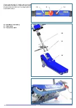
Page 47: ...y 15 Headrest control knob 16 Backrest control knob and hooks 17 Battery charger connector 18 Manoeuvring wheel 19 Rubber tracks 20 Control panel with key 21 Rear handle 22 Lower handlebar hook safety 23 Front handle 24 Balance point indication of masses 25 Wheelchair support 26 Lower handlebar release 1 2 25 5 6 4 3 9 7 8 10 11 13 15 14 12 16 22 23 24 21 20 26 19 18 17 BALANCE POINT The device ca...

Page 48: ...19 30 Handlebar hook safety 31 Fork clutch 32 Connection shaft The emergency button 11 must be used only under certain failure conditions or when the drive system should remain in motion even by releasing the UP and DOWN buttons ...

Page 49: ...ion If the key is disconnected or in 0 OFF position no electric function is enabled 2 Battery charge indicator see chapter battery charge 3 Aid back and forward button 33 Electric contacts handlebar side 34 Electric contacts motorised base side 35 Safety belts ...

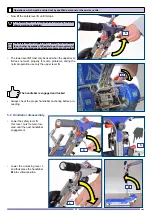
Page 50: ...is in up position lower the safety lever S and then the handlebar until it is engaged 5 1 Handlebar assembly M S A Clic Operations which must be carried out by qualified personnel or the service centre The device is supplied disassembled into two parts motorized machine unit and handlebar Caution Do not try to engage the handlebar on the rear shaft since the electric contacts may be damaged ...

Page 51: ... lower lever S1 must only be used when the upper lever S does not work properly for some problems during the normal operation use only the upper lever S 5 2 Handlebar disassembly S M S L S S1 Operations which must be carried out by qualified personnel or the service centre If the safety lever S is not positioned correctly the stair chairs working is disabled The safety levers S upper and S1 lower ...

Page 52: ...e centre L The lower lever L1 must only be used when the upper lever L does not work properly for some problems during the normal operation use only the upper lever L The wheelchair must be inspected and approved by the technician in charge of the manufacturer of stair chairs The unlocking levers L upper and L1 lower are con nected to each other by means of a flexible rope the movement of one leve...

Page 53: ...he wheelchair hook system until the crossbar T is in contact with the wheelchair handles Move the system until you hear a click safe locking click Together with the height you shall adjust the wheelchair locks by putting the plates P in contact with the whe elchair backrest frame Consequently pins Q will be inside the frame Each wheelchair handle will be placed between the pins Q and plates P Tigh...

Page 54: ...on Take out the brakes of the wheelchair Loosen the knob U and adjust the position of the headrest then tighten the knob 5 5 Adjusting the headrest The wheelchair is locked U 5 4 Wheelchair release B Operations which must be carried out by qualified personnel or the service centre Between the opening and closing positions there is a safety position that the user can find at about two mil limetres ...

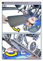
Page 55: ...53 EN Operations which must be carried out by qualified personnel or the service centre 5 6 Mounting and adjustment of the ramps on LG2004 150 A008 1 2 3 4 ...

Page 56: ...54 EN 5 6 OK NO 60cm 3 0 c m 7 Operations which must be carried out by qualified personnel or the service centre ...

Page 57: ...55 EN 8 9 10 Clic 11 12 Operations which must be carried out by qualified personnel or the service centre ...

Page 58: ...56 EN Operations which must be carried out by qualified personnel or the service centre 13 14 Clic ...

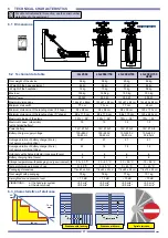
Page 59: ...y voltage 100 240 V 50 60 Hz 100 240 V 50 60 Hz 100 240 V 50 60 Hz 100 240 V 50 60 Hz Average duration of battery charge floors ref person weighing 80kg 27 27 27 27 Average duration of battery charge floors ref person weighing 130kg 22 18 18 12 Autonomy with charge indicator in reserve floors 4 4 4 4 Battery charging time hours 8 8 8 8 Storage temperature with packaging in dry environment 10 50 C ...

Page 60: ...cannot be used by persons operators who have not thoroughly read and understood the rules provided in this manual It cannot be used by operators with a slight physical build or who are not able to handle the total mass of the device The device cannot be used in areas subject to splashing water or critical and unfavourable weather conditions It must not be used in any case in which the principles d...

Page 61: ... charge it If after 8 hours batteries are not recharged check that the fuse is intact see chap Maintenance If the fuse is intact check the battery charger and if necessary replace batteries see chap Maintenance Batteries are special waste so they can be disposed of by specialist firms Before using each day always check the status of the device and the battery charge If the device will not be used ...

Page 62: ... to check the correct slope through the inclinometer When the whole track is on the stairs check the inclinometer and carefully comply with the following instructions 100 cm 35 max 70 cm max If the bubble lies within the green and red areas the slope is about 35 Operations which must be carried out by qualified personnel or the service centre If the bubble lies within the green area the slope is b...

Page 63: ... remove it from the aid the companion is responsible for the key Press the LIFTING button L so as to easily handle the stair chairs on the floor Open the wheel supports Place the stair chairs under the wheelchair and thus press one of the FORWARD or BACKWARD buttons to au tomatically reposition the stair chairs on the floor and in a firm position The motorised base can be moved even without handle...

Page 64: ...n stairs The person who operates this device on stairs both going up and down must possess a certificate of qualification issued by the manufacturer or an authorised representative only after having received direct theoretical and practical training and only after demonstrating the ability to safely perform all the operations described in this manual The operator and the passenger must be careful ...

Page 65: ...fter eliminating the cause that led the operator to press the emergency button release the button by turning the head in the direction indicated by the arrows printed on the same button Failure to the main motor system In case of a failure that makes the stair chairs inactive when used on stairs it is necessary Never unhook the wheel Try to ensure the maximum system stability Keep calm and ensure ...

Page 66: ...ou linearly and firmly Approach The operator may move the stair chairs closer to the staircase in two ways a by pressing the INDIETRO button The motor causes the stair chairs to stop while holding down the button b Operating it by hand after pressing the lifting button Near the stairs press the INDIETRO button to lower the tracks to the ground By releasing the button the stair chairs stop at any t...

Page 67: ... the ground The stairs have ended Turn the key of the panel to O OFF and remove it to ensure that no one other than the qualified operator can use the device Now the wheelchair can be released S4 The stair chairs are pulled towards the operator S5 The stair chairs are operated back to wards the operator ...

Page 68: ...T Press the AVANTI button and straightly take the stair chairs to the staircase and gradually put the aid out until the Balance point indicated on the base is nearly on the step edge Stop the stair chairs on the balance point Firmly hold the handlebar and release the stair chairs which will rotate towards the staircase you are ready for descent DESCENDING CYCLE D1 D6 D1 The stair chairs have reach...

Page 69: ...the wheelchair can be released Descent Press the AVANTI button the stair chairs will go down in front of you clearly and steadily By releasing the button the stair chairs stop at any time Continue to go down until you reach the landing D4 The stair chairs are going down D5 The stair chairs are in contact with the landing D6 The stair chairs are on landing ...

Page 70: ...s by hand Move the stair chairs closer to the loading surface Press the handlebar to lift the front up to the loading surface When the front rests firmly on the loading surface unhook the handlebar Hold the stair chairs one per son in front and another behind from the suitable handles After resting the stair chairs on the ground press the motion button to perform small move ments Risk of crushing ...

Page 71: ...ated Cleaning the wheels ref 9 3 Depending on use and necessity clean the parts indicated Cleaning the tracks ref 9 4 Depending on use and necessity clean the parts indicated 1 year General inspection check wheel functionality check track wear check brake system check that upholstery and padding is intact check that fastening screws are tightened check that tightening hand wheels of the various pa...

Page 72: ...ng a brush Rotate the aid completely on one side so that the handlebar rests on the ground this way you can access the underside Remove the material and dirt that may be on the tracks Along with this operation also check the wear state of the chocks of the two tracks If you find any damage including parts of missing chocks or wear beyond the set limits immedi ately inform the assistance centre to ...

Page 73: ...oxidized or damaged The safety lever is not inserted on the handlebar The fuse of 60A is burnt turn the key to I ON release the button check well the connection remove the handlebar and clean contacts check and insert well replace fuse Hoisting equipment Commands are not accepted The key is not in ON position The emergency button is pressed The handlebar is not properly inserted The handlebar cont...

Page 74: ...ls wear check safety levers wear check battery efficiency check wheelchair anchoring devices check the frame and wheel are intact check slope indicator check tracks and pulley check mechanical transmission system check headrest anchoring check safety belts check electrical handlebar contacts machine unit check and disinfection headrest and safety belts check control ropes check the machine body is...

Page 75: ...cks for pushchairs 12 OPTIONAL ACCESSORIES AVAILABLE UPON REQUEST ART A009 Anti overturning safety system ART A023 Standard hook ART A010 Extention cable for oversized wheelchair To install and use additional com ponents refer to the instructions enclosed with the equipment ...

Page 76: ...ignature of the assistance centre Date SCHEDULED MAINTENANCE 72 months Stamp and signature of the assistance centre Date SCHEDULED MAINTENANCE 36 months Stamp and signature of the assistance centre Date SCHEDULED MAINTENANCE 60 months Stamp and signature of the assistance centre Date SCHEDULED MAINTENANCE 84 months Stamp and signature of the assistance centre Date SCHEDULED MAINTENANCE 84 months S...

Page 77: ... signature of the assistance centre Date Description of the operation Stamp and signature of the assistance centre Date Description of the operation Stamp and signature of the assistance centre Date Description of the operation Stamp and signature of the assistance centre Date Description of the operation Stamp and signature of the assistance centre Date ...

Page 78: ...kaging expenses for any products under guarantee which must be shipped are to be paid by the customer The guarantee does not in any circumstances provide for compensation for damages Replacement parts are available for 10 years If the customer detects problems with the product s he must immediately notify the manu facturer or authorised representative in country and provide specific information re...

Page 79: ...E NR LRC 0271647 QMS COMPANY WITH CERTIFIED QUALITY CONTROL SYSTEM IN ACCORDANCE WITH UNI EN ISO 9001 2000 LLOYD S REGISTER QUALITY ASSURANCE APPROVAZIONE NR LRC 0271647 QMS 200711 Antano Group S r l Via Todi 15 Zona Ind le Matigge di Trevi 06039 Trevi PG Tel 0742 381269 Fax 0742 386574 www antanogroup com info antanogroup com ...

Reviews: