LIVING BY THE SUN!
MANUAL
I
3
1. Carry the Modules carefully and handle them on respecting of instruction.
2. Keep the Modules away from inflammable gas, hazardous chemicals or fire source.
3. Do not carry wet Modules.
4. It is highly recommended to transport with container and the unfilled space (the gap over 20cm) shall be filled
with inflatable bag; As for the non-container transport, the Modules shall be single laid and wholly cared, and
some effective measures shall be taken to prevent displacement.
5. The surface oxide layer of the border may be scratched by sharp objects, do not destroy or scratch the border
of the Modules.
1. Installers must be qualified engineers and familiar with electrical and its applications.
2. Do not use damaged Modules. Damaged Modules may cause fire or electric shock; both the two results could cause
the death of the user or installer.
3. Do not disconnect the cable under a load circumstance.
4. Under normal conditions, a Photovoltaic Module may be able to produce voltage and current higher than in standard
test condition. Accordingly, when determining component rated voltage, conductor ampacities, fuse current and size
of controls connected to the PV output, the short circuit current and open circuit voltage value marked on this
module shall be multiplied by a factor (safety factor) of 1.25.*
5. The Modules shall be installed in the position of the sun exposures fully and to ensure that not to be shaded by trees,
buildings or something others surrounding, such as in the northern hemisphere installed towards the south and in the
southern hemisphere installed towards the north.
6. Use the bracket structure that could withstand the pressure of high winds or heavy snow according to your practical
installation condition. The bracket structure must be made of durable, corrosion resistant, UV resistant materials.
7. The installation structure must be designed by registered professional engineers, and installation design and
procedures shall be consistent with the local relevant provisions.
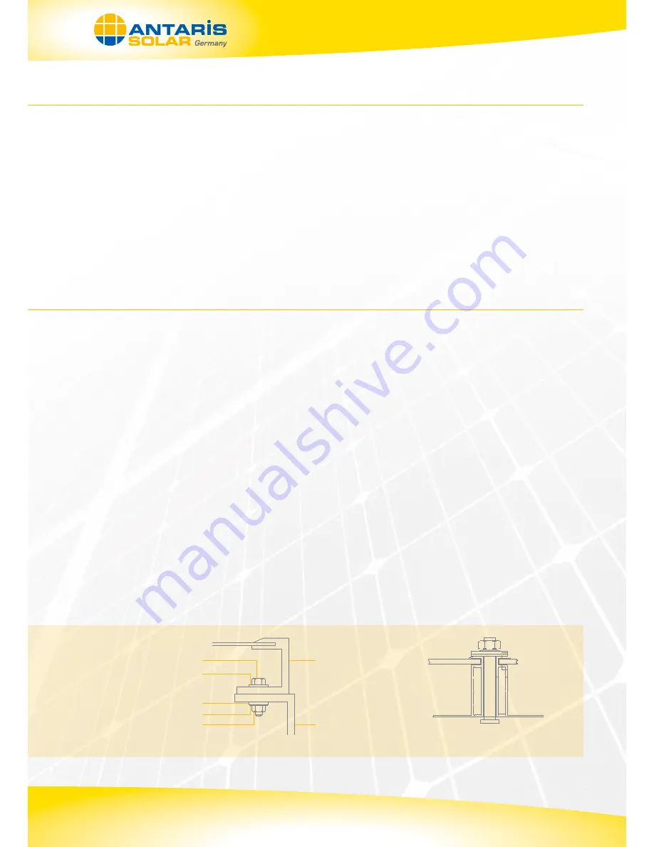
8. You could choose either fixing method mentioned below per the actual condition: Screw-fixing system (Drawing 1-a),
Fixture-fixing system (Drawing 1-b) or Inserting System.
Transport and Carry
Installation
SCREW BOLT
FLAT GASKET
FLAT GASKET
SPRING WASHER
SCREW NUT
MOUNTING STRUCTURE
Drawing 1-a Installed by nut and bolt
* Note: The safety factor for component rated voltage, conductor ampacities, fuse current and size of controls connected to the PV output is subject
to the meteorological conditions of project sites.
Drawing 1-b Installed by fixture
MODULE FRAME


