The Amp 2 comes with two (2) tubes, as follows:
6DJ 8/6 922 (V1) PH ASE IN VER TE R AND BUF FER
This amplification stage is switched into the circuit path
for both channels of the amplifier during bridged/mono
operation.
6DJ 8/6922 (V2) FIRST STAGE AMPLIFI CATI ON TU BE
The first stage of amplification in the Amp 2 is achieved
through the use of this dual triode, amplifying both channels,
one per triode section.
WARNING: Tube replacement and bias
adjustment involves working with the
covers off and power applied, around
hazardous and potentially lethal voltages,
and should be performed only by qualified
personnel with the proper equipment and
training.
S E T T I N G
U P
V 1
V 2
T R O U B L E S H O O T I N G
If at any time the Amp 2 fails to work properly, consult this
checklist:
1. Check that the AC Detachable Power Cord is plugged
into the Amp 2 Detachable Power Cord Socket (F) and is
connected to a live source of AC power. For instance, if using
a power bar, check that the bar is turned on.
2. Ensure that all Input and Output connections are secure for
a proper electrical contact.
3. DISCONNECT THE AC POWER CORD, wait 5 minutes and
check that:
• A slow-blo fuse (5 x 20mm fuse type), with a rating of 10
Amp/125V (5 Amp/250V for European and Asian versions), is
installed in the fuse holder.
• The AC power fuse is intact and has not blown. If the fuse has
blown, the thin metal conductor will have melted and the glass
may appear “smoked”. If the fuse has blown, replace with a
fuse of the same rating (10 Amp/125V slow-blo for 100 to 120
volt countries and 5 Amp/250V slow-blo for 220 to 240 volt
countries). (See Figure 6)
NOTE: Under no circumstances should you replace the AC
power fuse with one of a higher current rating! Doing so may
cause further damage to the Amp 2 and will also void the
warranty. In addition, your continued protection from risk of fire
or shock would be seriously compromised.
• Ensure the tubes are plugged firmly into their sockets as
described in “INSERTION OF THE TUBES”.
4. Be sure the rest of the system is functioning properly (i.e.
source unit, power amplifiers, cables and connections, etc.).
5. With tubes, fuses, covers and power cords in place, check
that the LED (A) is lighted (glowing light green). If all of the
above troubleshooting steps have been followed and the LED
is not lighted (remains dark green), contact your dealer or
distributor for assistance.
WARNING-DISCONNECT THE A C
D E TA C H A B L EP O W E RC O R D F R O M T H E
AMP 2 AND WAIT 5 MINUTES BEFORE
REMOVING COVER, TUBES OR FUSE.
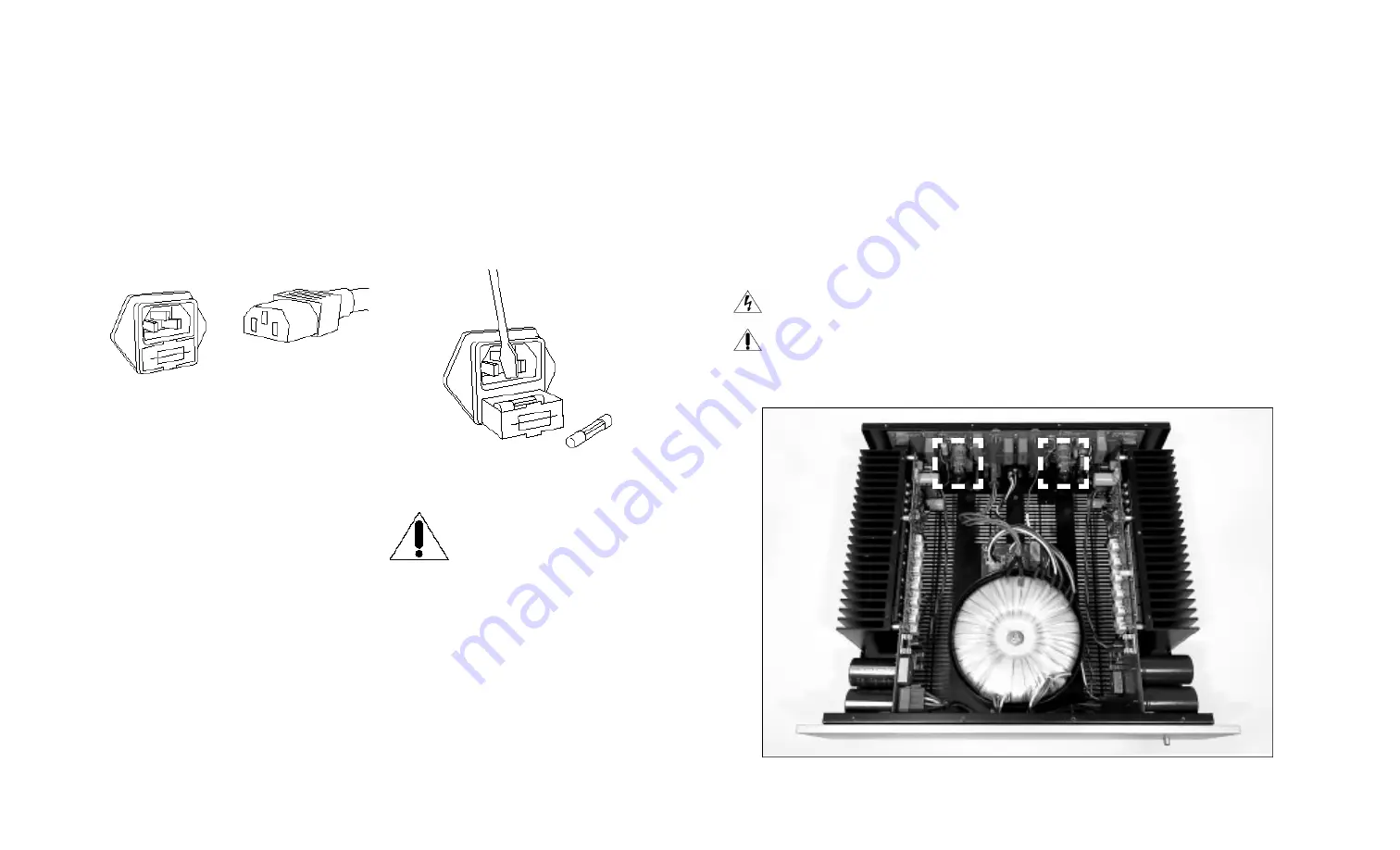
F I G U R E 5
Alignment of the AC power connector and detachable cord.
F I G U R E 6
Removal of the fuse holder.


