background image

89

MAIN 

Path (RCA & XLR output)

Frequency Response 

and

Bandwidth

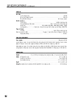
Analog-Direct Inputs . . . . . . . . . . . . . . . 10 Hz to 20 kHz (+0, -0.2 dB), 1 Hz to 130 kHz (+0, -3 dB)
Analog-DSP Inputs at 24/96 . . . . . . . . . . 10 Hz to 20 kHz (+0, -0.3 dB), 2 Hz to 44 kHz (+0, -3 dB)
Digital Inputs at 24/96 . . . . . . . . . . . . . . . 10 Hz to 20 kHz (+0, -0.2 dB), 1 Hz to 45 kHz (+0, -3 dB)

THD+N 

(at Rated Input & Output)

Analog-Direct Inputs . . . . . . . . . . . . . . . . . . . . . . . . . . . . . . . . . . . . . . . . . . . . . . 0.006% (80 kHz BW)
Analog-DSP Inputs at 24/48 or 24/96 . . . . . . . . . . . . . . . . . . . . . . . . . . . . . . . . 0.004% (AES17 filter)
Digital Inputs at 24/48 or 24/96 . . . . . . . . . . . . . . . . . . . . . . . . . . . . . . . . . . . . . 0.004% (AES17 filter)

IMD

(CCIF at 15 kHz & 16 kHz)

Analog-Direct Inputs . . . . . . . . . . . . . . . . . . . . . . . . . . . . . . . . . . . . . . . . . . . . . . . . . . . . . . . . <0.001%
Analog-DSP Inputs at 24/48 . . . . . . . . . . . . . . . . . . . . . . . . . . . . . . . . . . . . . . . . . . . . . . . . . . . . 0.001%
Digital Inputs at 24/48 or 24/96 . . . . . . . . . . . . . . . . . . . . . . . . . . . . . . . . . . . . . . . . . . . . . . . . . 0.001%

S/N Ratio 

(ref. 2.0 Vrms, IEC-A filter)

Analog-Direct Inputs . . . . . . . . . . . . . . . . . . . . . . . . . . . . . . . . . . . . . . . . . . . . . . . . . . . . . . . . . . 107 dB
Analog-DSP Inputs at 24/48 or 24/96 . . . . . . . . . . . . . . . . . . . . . . . . . . . . . . . . . . . . . . . . . . . . 101 dB
Digital Inputs at 24/48 or 24/96. . . . . . . . . . . . . . . . . . . . . . . . . . . . . . . . . . . . . . . . . . . . . . . . . . 104 dB

ZONE2 

and

ZONE3 

Paths

Frequency Response 

and

Bandwidth

. . . . . . . . 20 Hz to 20 kHz (+0, -0.1 dB), 3 Hz to 140 kHz (+0, -3 dB)

THD+N 

(at Rated Input & Output) . . . . . . . . . . . . . . . . . . . . . . . . . . . . . . . . . . . . . . . . . . . . 0.06% (80 kHz BW)

IMD

(CCIF at 15 kHz & 16 kHz). . . . . . . . . . . . . . . . . . . . . . . . . . . . . . . . . . . . . . . . . . . . . . . . . . . . . . . . . . . 0.06%

S/N Ratio 

(ref. 2.0 Vrms, IEC-A filter) . . . . . . . . . . . . . . . . . . . . . . . . . . . . . . . . . . . . . . . . . . . . . . . . . . . . . 97 dB

FM TUNER

Sensitivity 

50 dB S/N. . . . . . . . . . . . . . . . . . . . . . . . . . . . . . . . . . . . . . . . . . . . . . . . . . . . 13 dBµ typ., 25 dBµ max.
IHF. . . . . . . . . . . . . . . . . . . . . . . . . . . . . . . . . . . . . . . . . . . . . . . . . . . . . . . . . . 10 dBµ typ., 20 dBµ max.

S/N Ratio 

Mono . . . . . . . . . . . . . . . . . . . . . . . . . . . . . . . . . . . . . . . . . . . . . . . . . . . . . . . . . . 75 dB typ., 65 dB min.
Stereo . . . . . . . . . . . . . . . . . . . . . . . . . . . . . . . . . . . . . . . . . . . . . . . . . . . . . . . . . 69 dB typ., 60 dB min.

Distortion 

Mono . . . . . . . . . . . . . . . . . . . . . . . . . . . . . . . . . . . . . . . . . . . . . . . . . . . . . . . . . . . 0.2% typ., 1.0% max.
Stereo . . . . . . . . . . . . . . . . . . . . . . . . . . . . . . . . . . . . . . . . . . . . . . . . . . . . . . . . . . 0.3% typ., 1.5% max.

Stereo Separation

. . . . . . . . . . . . . . . . . . . . . . . . . . . . . . . . . . . . . . . . . . . . . . . . . . . . . . . 40 dB typ., 25 dB min.

Alternate Channel Selectivity 

(±400 kHz) . . . . . . . . . . . . . . . . . . . . . . . . . . . . . . . . . . . 70 dB typ., 60 dB min.

Frequency Response

. . . . . . . . . . . . . . . . . . . . . . . . . . . . . . . . . . . . . . . . . . . . . . . . . 25 Hz to 15 kHz (+0, -2 dB)

AM TUNER

Sensitivity 

(20 dB S/N) . . . . . . . . . . . . . . . . . . . . . . . . . . . . . . . . . . . . . . . . . . . . . . . . 49 dBµ typ., 56 dBµ max.

S/N Ratio

. . . . . . . . . . . . . . . . . . . . . . . . . . . . . . . . . . . . . . . . . . . . . . . . . . . . . . . . . . . . . . . 50 dB typ., 43 dB min.

Distortion

. . . . . . . . . . . . . . . . . . . . . . . . . . . . . . . . . . . . . . . . . . . . . . . . . . . . . . . . . . . . . . . . 0.7% typ., 2.0% max.

One Signal Selectivity 

(±10 kHz) . . . . . . . . . . . . . . . . . . . . . . . . . . . . . . . . . . . . . . . . . . 24 dB typ., 18 dB min.

SPECIFICATIONS 

continued …

Summary of Contents for Statement D2v

Page 1: ...STATEMENT D2v OPERATING MANUAL UPDATES www anthemAV com S O F T W A R E V E R S I O N 2 0 x...

Page 2: ...EDUCE THE RISK OF ELECTRIC SHOCK DO NOT REMOVE COVER OR BACK NO USER SERVICEABLE PARTS INSIDE REFER SERVICING TO QUALIFIED SERVICE PERSONNEL RISK OF ELECTRIC SHOCK DO NOT OPEN WARNING 1 Read Instructi...

Page 3: ...kely to be walked on or pinched by items placed upon or against them paying particular attention to cords at plugs convenience receptacles and the point where they exit from the product 12 Outdoor Ant...

Page 4: ...m Electronics Inc the manufacturer of Paradigm speakers and Anthem electronic products has arranged with its distributors in European Union member nations to collect and recycle this product at no cos...

Page 5: ...11 2 6 IR Infra Red Emitters 11 2 7 Power 11 3 SETUP Entering Navigating Exiting the Setup Menu 15 3 1 Video Output 16 3 2 Set Time and Timers 21 3 3 Speaker Configuration 24 3 4 Listener Position 29...

Page 6: ...el sources 60 4 8 8 Mode and THX options for 5 1 channel Dolby sources and 6 Ch S E 61 4 8 9 Mode and THX options for 5 1 channel DTS sources 62 4 8 10 Dynamics 63 4 9 Lip Sync Delay 63 4 10 Display B...

Page 7: ...re Updating Via Your Dealer 78 6 3 Software Updating Via Your Computer and the Internet 78 Appendix A IR Macros for Surround Modes and FM AM Banks 80 Appendix B Preset Memory Codes 81 Specifications 8...

Page 8: ......

Page 9: ...opic stand Serial extension cable USB microphone cable Base Safety Instructions Read all precautions and instructions at the beginning of this manual Do not connect power if there are signs of damage...

Page 10: ...p and headphone access 8 Power on standby 9 Mute 10 Status review setup menu access 11 Balance setting 12 Bass treble settings 13 LED and display brightness setting video adjustment menu access 14 Fro...

Page 11: ...FM1 FM2 and FM3 and one AM bank 2 FM mode Displays St when in stereo HB when in Hi Blend or Mn when in mono 3 Seek and scan indications 4 Frequency FM is tuned to the nearest 0 1 MHz AM is tuned to ne...

Page 12: ...2 Main audio output 10 balanced jacks 13 3 IR extension inputs with 12V supply 14 RS 232 interface bidirectional 15 Main audio output 10 jacks 16 6 channel analog audio input 17 AES EBU digital audio...

Page 13: ...tment for balance and lip sync 10 THX selection 11 FM AM preset up down 12 Sleep timer selection timers setting 13 Volume up down and mute 14 Channel selection for level bass treble and balance 15 Num...

Page 14: ...N Z2 Z3 AVM PATH DYNAMICS VOLUME CH PRE SET FM AM PRE SETS SEEK TUNE SOURCE SEEK L EA RN ENTER MUTE 7 80 9 SELECT SUB LFE FM AM SUR RR AVM OFF DISP LAY T O NE BYPASS MO DE O N SCREEN O F N I E D I U G...

Page 15: ...works at 1080p24 may not work at 1080p50 or 1080p60 BE CAREFUL WHEN MAKING HDMI CONNECTIONS The connector should easily slide in the jack do not insert it on an angle and do not force it Each connecto...

Page 16: ...ed in MAIN processed or unprocessed or in ZONE2 S Video Maximum resolution is 480i NTSC 576i PAL This connection keeps brightness and color separate for a better picture than Composite S Video input c...

Page 17: ...d video from the source ZONE2 ZONE3 and RECORD require analog connection unless set to copy MAIN explained in sections 3 6 and 4 3 6 Ch Analog Input The 6 Ch input is for connecting DVD Audio and mult...

Page 18: ...to ensure noise rejection if the ZONE2 amplifier has balanced input and it s at a distance from the processor see section 3 9 If you re using one rear channel use the Rear L output to connect it see...

Page 19: ...rs allow the remote control to be used from other locations in your home Once an IR receiver is wired to another room connect it to one of the three IR RECEIVER inputs through the removable terminal b...

Page 20: ...t if using ZONE2 Cable and satellite receivers HDTV receivers can be connected as above although HDMI connection may be problematic with older models especially when output resolution changes between...

Page 21: ...sor VCR EJECT AUDIO OUT L R AUDIO IN For ZONE2 ZONE3 and REC in most cases you must use the same input type as the output type If MAIN uses a different input connection all you need to do is add these...

Page 22: ...ction shown single ended is similar WARNING To powered subwoofer WARNING Trigger Setup Suggestion If it is not necessary to have both amplifiers turned on when stereo sources are playing set triggers...

Page 23: ...nnection and a program from our web site called Setup Editor This can also save your configuration as a backup file Setup Editor cannot play test signals calibration still has to be done through the s...

Page 24: ...DMI1 output by default On screen display comes from HDMI2 and Component processed if Preferred is changed to Component in menu 1 submenus S Video on screen display is available in both cases ZONE2 on...

Page 25: ...the line that s highlighted in the VIDEO OUTPUT menu Highlighting VIDEO OUT CONFIG 1 in the VIDEO OUTPUT menu then pressing SELECT displays this menu Items a through g pertain to MAIN output only Chan...

Page 26: ...material on disc is natively 1080p24 or 1080i60 if your player has a passthrough mode where output resolution and refresh rate follow that of the source you can use it with Configuration 1 resolution...

Page 27: ...24 Hz or 50 Hz or 60 Hz Custom Auto high bandwidth cable is required Color Space Set this to match your display type HDTV high definition TV SDTV standard definition or Auto Data Format Select YCbCr...

Page 28: ...11 Synchronization Try Inverted setting if the image via HDMI is not centered or does not show typically needed only with some older displays Component 2 Out The second Component video output can be c...

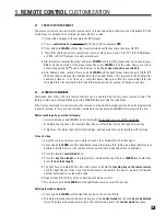
Page 29: ...the Master Control Knob or the 56 buttons to set current minutes Press BACK to return to the menu line Press the 6 button to go to DAY then use the 3 4buttons to set the current day All Timers This a...

Page 30: ...OFF Sets the Saturday and Sunday turn off time Timers may also be set to only turn on or only turn off see Example 2 this way the processor can be set to turn on automatically and it won t turn off un...

Page 31: ...ocedure is the same for MAIN ZONE2 and ZONE3 Example 2 Change ZONE2 TIMER2 to come on Weekdays at 7 30 AM Enter the setup menu Go to SET TIME TIMERS and press SELECT Press the 6 button until you reach...

Page 32: ...ipole speakers since most of the sound is delayed through room reflections When Dipole is selected distance is matched internally with the greatest one in the LISTENER POSITION menu If you are using o...

Page 33: ...bove except bass from all channels is included not just the ones set to Small This setting is not recommended for the Movie configuration 2 Subs or 2 Supers Select if using both subwoofer outputs and...

Page 34: ...bass If room acoustics cause response to drop in the crossover region the subwoofer channel can be set to overlap other channels to compensate for instance setting SUB LFE XOVER to 90 Hz and FRONTS X...

Page 35: ...when the built in test tones are played If you re using a sound pressure level meter set it to C weighting or Flat Filter Depth This is the amount of center frequency cut or reduction in volume in th...

Page 36: ...igher levels In addition it can be quite difficult to hear these frequencies If playing them causes unusual sounds indicating the subwoofer is being stressed do not continue to play them TEST FREQ cha...

Page 37: ...peaker Range is 0 99 ft in 0 5 ft increments or 0 32 m in 0 2 m increments Example Set center speaker distance to 11 feet Enter the setup menu Go to LISTENER POSITION and press SELECT Press the 6 butt...

Page 38: ...ts are necessary when using ARC Test Noise Sequence Test noise plays from one speaker at a time changing manually using the 56 buttons or automatically every two seconds by setting NOISE SEQUENCE to A...

Page 39: ...ned result of 75 dB SPL To fine tune the level or phase of each sub relative to one another listen to FM shhhh noise through the subwoofers only turn off main amplifiers and adjust the sub s control u...

Page 40: ...ers with different sources when you have more than nine source components To enable DVD2 DVD3 DVD4 TV2 TV3 TV4 or SAT2 at the top of its submenu change SAME AS to Custom to create its own Source Setup...

Page 41: ...ll be highlighted in red Press SELECT The first character A will be highlighted in red Use the Master Control Knob or the 56 buttons to change characters Change the first one to G Press the4 button to...

Page 42: ...to digital inputs including Anthem Room Correction bass management time alignment surround mode bass treble lip sync delay and THX If you want your subwoofer to play from an analog L R input use this...

Page 43: ...s management configurations and the same player for DVDs and CDs Room EQ MAIN only To disable room correction equalization performed with the ARC 1 microphone kit change this to Off If measurement inf...

Page 44: ...one see sections 4 8 4 and 4 8 6 The following apply to Digital inputs only 2 0 Sur Separate setting especially for surround flagged Dolby Digital 2 0 material section 4 8 2 normally PLIIx Movie but a...

Page 45: ...less remaining indicator Before making changes or adjustments in this menu have all source components playing music with comparable dynamics As you switch highlighted source you will hear that compone...

Page 46: ...ting When copied from MAIN to RECORD the output is a 2 channel downmix Bit Rate of DIGITAL1 when MAIN is copied to REC Choose from 16 or 24 bit output to match the recorder At 16 bits dither is added...

Page 47: ...95 5 dB to 31 5 dB in steps of 5 dB and for ZONE2 ZONE3 and HEADPHONE the range is from 70 0 dB to 10 0 dB in 1 25 dB steps To set a fixed output for ZONE2 or ZONE3 scroll MAX VOL past 10 0 dB to sel...

Page 48: ...sed by switching on too many devices at once All Triggers When Disabled all triggers remain off When Enabled the trigger chart below is used to set conditions For custom installation the RS 232 Ctrl s...

Page 49: ...e room as the processor In this case the processor can receive two IR signals for the same command one through the front and one through the back The double command may affect responsiveness disabling...

Page 50: ...for example while adjusting ZONE2 yourself from the MAIN room Main Z2 On Screen Position Allows you to position the on screen display to reduce the chance of it interfering with the on screen display...

Page 51: ...able the front panel wakeup Enter the setup menu Go to DISPLAYS TIMEOUT and press SELECT Press the 6 button until you reach FP WAKE UP Use the 3 4buttons to change to None When finished press 56 to go...

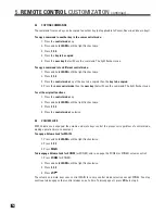
Page 52: ...enu item SAVE USER SET NS will be highlighted in red Press SELECT You will be asked to confirm that you want to over write current settings Use the 3 4 buttons and change to Yes If you are using a Pas...

Page 53: ...mote control only Enter the setup menu You must enter the USER or INSTALLER password if there is one Go to LOCKOUT PASSWORDS and press SELECT Press the 6 key to go to SET USER PASSWORD Press SELECT Yo...

Page 54: ...lattened bass sounds thin Ideal anechoic speaker response a straight line as measured in a special non reverberant facility is not the same as ideal in room response which normally includes to varying...

Page 55: ...adapters load bad data into the processor possibly causing its operation to freeze 3 The virtual port must be assigned to COM1 COM6 If the processor software installer cannot locate the processor use...

Page 56: ...to be adjusted and measurements repeated To adjust the length of the telescoping tube first loosen its clamp by rotating it counterclockwise Five listening area positions are normally measured but thi...

Page 57: ...frequency with the cursor and Backspace key on the computer s keyboard Removing the center or surround speakers is not necessary for listening to 2 channel sources in stereo if a surround mode is not...

Page 58: ...at is not connected via L R analog audio you must copy it from MAIN see section 4 3 RECORD Except when prevented by copy protection allows you to record sources independently of what is selected in ot...

Page 59: ...the left and right channels for the processor s non MAIN outputs This can be done by the source or the processor Processor downmix The processor downmixes multichannel sources into 2 0 when you copy M...

Page 60: ...this while scanning for stations The lower line of the display briefly flashes once the station is stored To skip a preset set it to 87 5 FM or 530 AM To recall a preset select the bank that it is in...

Page 61: ...lower levels can result in quiet sounds disappearing into the noise floor Dialog Normalization also ensures that Dynamics control section 4 8 10 works as intended If the display reads Dial Norm Offse...

Page 62: ...ories those that apply to stereo sources and those that apply to multichannel sources By default all surround speakers are used except with 1 0 channel sources after finding your preferences change pr...

Page 63: ...sive listening tests a very effective design was developed This is also a minimalist design that avoids the use of echo effects which could otherwise negatively affect the purity of the sound Up to 7...

Page 64: ...movies and TV programs Pro Logic IIx Matrix 7 1 A matrix decoder that does not steer the image from one speaker to another Pro Logic IIx Game 7 1 Bass from surround effects in video games is optimize...

Page 65: ...te at www thx com A flag to engage Dolby Digital EX or Pro Logic IIx is usually contained in newer titles Press MODE when a movie starts playing and use the Master Control Knob to select the mode that...

Page 66: ...t s coming from Movie theatres use an array of surround speakers resulting in surround information from many directions In the home less surround speakers are used Timbre Matching which includes Re EQ...

Page 67: ...THX Surround EX Dolby Digital Surround EX is a joint development of Dolby Laboratories and the THX division of Lucasfilm Ltd In a movie theater film soundtracks encoded with Dolby Digital Surround EX...

Page 68: ...norama On using MCK or N S keys Extends the front stereo image to include surrounds 4 8 7 Mode and THX options for 2 0 channel sources THX Press THX Press THX Twice LOGIC LOGIC THX Cinema 5 1 Re EQ Ti...

Page 69: ...ltra2 Cinema 7 1 Re EQ Timbre Adaptive Decorrelation ASA Cinema THX Press THX Twice RE EQ On Off using MCK or N S keys Press THX THX MusicMode 7 1 Timbre Matching Adaptive Decorrelation ASA Music THX...

Page 70: ...ons are memorized separately for DTS vs DTS ES Matrix THX Cinema is the only option for 6 1 and 7 1 channel sources Re EQ Timbre Matching THX Press THX Press THX Twice THX Cinema 7 1 Re EQ Timbre Matc...

Page 71: ...range controls as well Be sure to disable them to get the most from the processor s dynamics control In some cases the setting names in sources are confusing because Extended can mean dynamics are lef...

Page 72: ...ts so set them up first for example set your DVD player s output to 16 9 HOW TO ENTER THE VIDEO PROCESSING MENU For three seconds press and hold ON SCREEN 7 on the remote or DISPLAY on the front panel...

Page 73: ...utput in menu1 is set to RGB Color and Tint are not adjustable so that unnecessary color space conversion is avoided If you need to adjust the image in such a case set the source component to YCbCr ou...

Page 74: ...such an artifact but don t spend energy looking for it your DVD player depending on model may have it taken care of Video ADC S Video and component video signals containing anomalies may need adjustm...

Page 75: ...can be adjusted after size is adjusted this can also be the right choice for off center sources but in this case be sure to adjust size proportionally you can use a geometry test pattern for a visual...

Page 76: ...ty The shade of the empty areas can be adjusted in menu 1 Not applicable when input is 720p or higher No Scaling To quickly check what the source component is putting out in unscaled form select No Sc...

Page 77: ...CROP INPUT 16 9 SCALE OUTPUT Anamorphic Stretch Standard definition 4 3 source Stretch sides more than center CROP INPUT Auto Detect SCALE OUTPUT Panoramic Stretch Standard definition 4 3 source Stre...

Page 78: ...Anamorphic SD DVD 2 4 1 source Crop and or stretch to fill screen CROP INPUT Custom adjust to taste SCALE OUTPUT Anamorphic Stretch Hi definition 2 4 1 source Crop and or stretch to fill screen CROP I...

Page 79: ...e source If your display accepts various refresh rates and your disc player has passthrough mode you can also use Frame Lock to match refresh rate to the source material 24 Hz 50 Hz 60 Hz overriding t...

Page 80: ...display has DVI input ensure that the correct output between Studio and Extended RGB is selected in menu 1 The best setting for the display s sharpness control is usually at its lowest even when the d...

Page 81: ...tting your display s color and tint Looking through the blue filter or glasses adjust color saturation so that areas C match as closely as possible then adjust tint hue so that areas D match as closel...

Page 82: ...through display screens that show the following Software version day and time Video Input Resolution and refresh rate of video source and copy protection status if available CP means copy protected NP...

Page 83: ...ore pressing the taught key If the factory command is used more than the learned command the learned command can be programmed in Layer2 instead In this case the learned command is sent by pressing LE...

Page 84: ...ey that will have the command The light flashes twice To set the original functions 1 Press the control mode key 2 Press and hold LEARN until the light flashes twice 3 Press 9 9 4 4 Press the control...

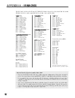
Page 85: ...mode 1 Press the control mode key 2 Press and hold LEARN until the light flashes twice 3 Press 9 7 8 4 Press the key you want to use to activate your macro e g Power 5 Enter the command sequence that...

Page 86: ...aler the dealer may charge for this service 6 3 SOFTWARE UPDATING VIA YOUR COMPUTER For computer and connection requirements see section 3 15 Software installation 1 Find out which version is installe...

Page 87: ...79...

Page 88: ...x Movie MODE 7 7 PLIIx Movie THX Cinema MODE 7 8 PLIIx Music MODE 7 9 Dolby Digital EX MODE 8 0 Neo 6 MODE 8 1 Neo 6 THX Cinema For 6 1 and 7 1 channel sources THX 6 0 None THX 6 1 THX Cinema For DTS...

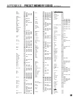
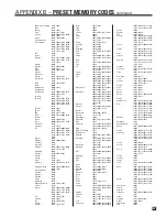
Page 89: ...0 30100 31364 30185 Sugden 30157 Sylvania 30157 Symphonic 30180 30305 TAG McLaren 30157 Tandy 30032 Tascam 30393 30420 Teac 30490 30180 30378 30393 30420 Technics 30029 30303 Techwood 30303 Thule Audi...

Page 90: ...79 21479 Calix 20037 Candle 20037 20038 Canon 20035 Capehart 20002 20020 20062 Carrera 20240 Carver 20035 20081 CCE 20072 20278 Cineral 20278 Citizen 20035 20037 20240 20000 20209 20278 20479 21278 Cl...

Page 91: ...dy 20000 20104 Tatung 20048 20081 20000 20067 20041 20008 Teac 20000 20067 20041 Technics 20035 20162 20037 20000 Teknika 20035 20037 20000 Telecorder 20240 Telefunken 20041 20208 Tevion 20479 Thomas...

Page 92: ...3 00144 Scientific Atlanta 01877 00877 00477 00237 00003 00000 00008 00012 00017 01510 Sony 01006 01460 Sprucer 00144 Starcom 00003 00014 Stargate 00014 Storm 00637 Sumitomo 01500 Supercable 00276 Sup...

Page 93: ...0854 10855 11154 Matsui 10177 Matsushita 10250 10051 10650 Maxent 11755 11756 Megapower 10700 Megatron 10047 10178 10145 10151 MEI 10185 Memorex 10154 10463 10180 10150 10178 10030 10165 11926 MGA 101...

Page 94: ...ombos Advent 11933 Akai 11935 Apex Digital 11943 Audiovox 11937 11951 11952 Axion 11937 Broksonic 11935 Hitachi 11960 Jensen 11933 Panasonic 11941 Prima 11933 RCA 11948 11958 Samsung 11903 Sansui 1193...

Page 95: ...1469 31801 Sharp 30186 30771 31286 Sharper Image 31556 Sherwood 30491 30502 31077 31423 31517 31653 Shinsonic 31426 Sirius 31602 31627 31811 31987 Sonic Blue 31532 31869 Sony 31058 31441 31258 31759 3...

Page 96: ...5 dB increments Zone2 3 and Headphone 62 5 to 10 0 dB in 1 25 dB increments Crosstalk at 1 kHz 82 dB between channels 86 dB between inputs XLR Pin Configuration Pin 1 Ground Pin 2 Positive Pin 3 Negat...

Page 97: ...uts 107 dB Analog DSP Inputs at 24 48 or 24 96 101 dB Digital Inputs at 24 48 or 24 96 104 dB ZONE2 and ZONE3 Paths Frequency Response and Bandwidth 20 Hz to 20 kHz 0 0 1 dB 3 Hz to 140 kHz 0 3 dB THD...

Page 98: ...ion Maximum 170 W Low voltage version In countries where the line voltage is 120V this product operates from a single phase AC power source that supplies between 108V and 132V at a frequency of 60 Hz...

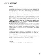
Page 99: ...determine the cause of the problem and arrange for the appropriate action Alternatively follow the procedure below for factory service A Return Authorization RA number must be obtained from Anthem Te...

Page 100: ...THE BIG PICTURE FRONT PANEL...

Page 101: ...THE BIG PICTURE REAR PANEL...

Page 102: ...D E S I G N E D A N D M A N U F A C T U R E D I N N O R T H A M E R I C A t e l 1 905 362 0958 M F 9 0 0 a m 5 3 0 p m E T w w w a n t h e m A V c o m 1 2 1 0 9 O M 1 0 0 2...

Reviews: