background image

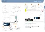
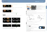
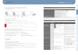
7.2.3 - How to pair the pedal with the unit  

1 - Press on the pedal lever.  
2 - Press the 3 green buttons on the screen at the same time. 


3 - The logo 

   flashes until the pairing is complete (time to achieve pairing = about 30 sec) 

4 - Press the 2 end buttons on the pedal.  
5 - A beep at the console confirms the pairing : the logo 

  disappears and the logo 

  is 

displayed.  


If after all these actions, the pictogram remains lit, see the section “Anomalies and errors” 


7.2.4 - How to place the pedal in extended standby.  


If you don’t plan to use your motor for an extended period of time (> 30 days), or you wish to 

transport it by air, placing the pedal in extended standby mode is recommended. 


To do so, just press on the 3 pedal buttons simultaneously. 


The persistent display of the symbol 

   on the screen confirms that the pedal is on standby.  


To leave standby mode, just press on the pedal lever (see start of section 7.2.1). 


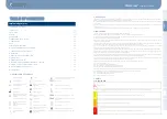
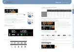
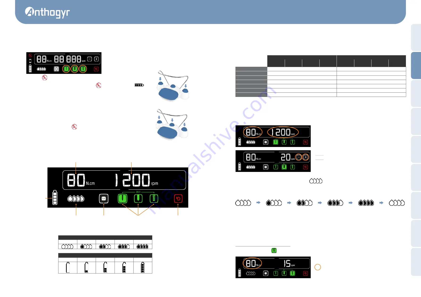
8.1. DEFINITION OF THE DISPLAY 


* the coloured square indicates the current program. 

8. USE 

Programmed maximum 

torque (N-cm) 

Programmed maximum 

speed (rpm) 

Charge level of the 

pedal battery 

Reverse operation 

Implantology sequence 20 :1  

Drilling / tapping / screwing  

Program 1 :1 

Irrigation flow rate  

Pump  

0% 

25% 

50% 

75% 

100% 


Battery 

0% 

25% 

50% 

75% 

100% 


*


a

®


EN - 

USER GUIDE


Fr

an

çais


Engli

sh


D

eu

tsc

h


Esp

ol


Ita

li

an

o


Portu

gu

ês


Ne

d

erl

an

d

中国的


   رع


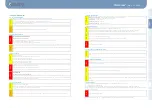
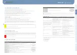
8.2 PARAMETERS OF PROGRAMS (FACTORY SETTING) 

To select a program on the screen, press on the pictogram of the selected program. For navigation to the pedal between the implantology 
sequence programs, see para. 8.5. 

At the startup, the program "drilling" is active. The program parameters can be changed by following the instructions given below.  

* The range of setting from 5 to 80 N-cm. These values are valid only for the contra-angles of the MontBlanc

®

 Implant series (10400X-XL / 16400X-XL). 

With 

these contra-angles, the accuracy of torque is ± 10% for the range from 5 to 80 N.cm.


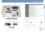
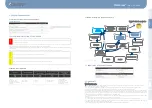
8.3. SETTING THE VALUES OF SPEED / TORQUE / FLOW RATE 

8.3.1 - Setting the rotation speed and the maximum torque 

1 - Pressing on the parameter to be changed (speed or torque).  

2 - The parameter starts flashing and the b/- appear. 

3 - Adjust the value of the parameter with the b or 

4 - Press on the parameter to validate. The parameter stops flashing. 
5 - The parameter automatically stops flashing after 5 seconds and the 
set value is saved.   

NOTE 1 : Value of the parameter is saved permanently for the program. 

NOTE 2 : You cannot operate the pedal during the setting of the parameters.  


8.3.2 - Setting the irrigation flow rate 

For setting the irrigation flow rate, press on the pictogram 

Each press increases the flow rate by 25% (display of an additional drop). 

At 100%, an additional press makes the irrigation flow rate 0%. 

To cut off the irrigation and reset to a given flow rate, use the ON / OFF function of the pedal. (See paragraph 8.5). 


8.4. DISPLAY OF THE LAST TORQUE REACHED 

The XPERT UNIT

®

 motor allows you to validate the tightening torques to be saved. These torques will be exported with the mobile app 

XPERT UNIT

®

 and used on the web portal.  

 
Displaying and saving the tightening torques  

In tightening mode, (button 

lit up) when the motor has stopped, the torque displayed is the maximum torque programmed (Screen 

A).


In normal mode  

In reverse mode  


20 :1  

Drilling  

20 :1  

Tapping  

20 :1  

Screwing  

Ratio 1 :1 

20 :1  

Drilling  

20 :1  

Tapping  

20 :1  

Screwing  

Ratio 1 :1 

Speed (rpm) 

1200 

20 

15 

40 000 

2000 

40 

30 

15 000 

Torque * (N.cm) 

80 

80 

80 

80 

80 

80 

80 

80 

Direction of rotation  

right  

right  

right  

right  

left  

left  

left  

left  

Pump  

100% 

100% 

0% 

100% 

0% 

0% 

0% 

0% 

Display of the torque  

NO 

YES 

YES 

NO 

NO 

YES 

YES 

NO 

Display of the speed  

YES 

YES 

YES 

YES 

YES 

YES 

YES 

YES 

Beep  

YES 

YES 

YES 

YES 

0% 

Press 

25% 

Press 

50% 

Press 

75% 

Press 

100% 

Press 

0% 


Summary of Contents for Xpert Unit

Page 1: ...bcdef ghij EN User manual ...

Page 2: ...at you have placed in it In order to get complete and sustainable benefit from this product it is recommended that you read this user manual first and perform the recommended inspection and maintenance tasks This Anthogyr product is used exclusively with the accessories provided by Anthogyr micromotor pedal power supply cable The use of any other accessory is prohibited This equipment is compatibl...

Page 3: ...f the manufacturers for the instrumentation used This is to limit the risk of injury and deterioration of instruments ATTENTION Once the servicing work is completed switch off the device Unplug it from the electrical mains in the event of prolonged non use WARNING a EN USER GUIDE Français English Deutsch Español Italiano Português Nederlands 中国的 عر 4 2 5 Storage conditions 4 2 6 Peristaltic pump 4...

Page 4: ...e Position 0 6 2 CONNECTION DISCONNECTION OF THE MICROMOTOR Align the red dot of the micromotor socket to the red dot of the connector on the front face of the cabinet and clipper Technical Specifications Dimensions Cabinet w x d x h 243 x 222 x 102 mm Pedal l x d x h 280 x 170 x 70 mm Micromotor Ø x l Ø23 x 115 mm Micromotor cable l 2 m Cabinet 2 5 kg Weight Pedal 1 kg Micromotor 110 g Micromotor...

Page 5: ...position I At startup all the pictograms on the screen light up and the device emits a beep The code Er02002 at startup means there is an anomaly with the date and time The date and time synchronise automatically with the mobile app when you are connected 7 2 WIRELESS PEDAL CONNECTION 7 2 1 At the 1st use At unit startup the pictogram display means that the pedal is on standby Press on the pedal l...

Page 6: ...ngles of the MontBlanc Implant series 10400X XL 16400X XL With these contra angles the accuracy of torque is 10 for the range from 5 to 80 N cm 8 3 SETTING THE VALUES OF SPEED TORQUE FLOW RATE 8 3 1 Setting the rotation speed and the maximum torque 1 Pressing on the parameter to be changed speed or torque 2 The parameter starts flashing and the buttons appear 3 Adjust the value of the parameter wi...

Page 7: ... flashes indicating the need to recharge soon see instructions below When charge level of the battery reaches 0 the device will beep every 30 seconds and it is not possible to use the motor Recharge according to the following instructions 8 7 RECHARGING THE PEDAL BATTERY Connect the charging adapter to the pedal through the connector located at the rear of the pedal Connect the adapter to the main...

Page 8: ...ect for a period of 24 months from the date of invoice This warranty does not apply to wearing parts Any modification or addition to the product without the express consent of the company Anthogyr will nullify this warranty The warranty will lapse in case of non observance of the technical instructions provided with all our devices Anthogyr cannot be held responsible for damages and their conseque...

Page 9: ... problem per sists do not use the motor pedal micro motor any longer Contact the Anthogyr After Sales Service for more infor mation Er 02 005 The touch bar encounters operating problems The micromotor pedal micromotor assembly can still be used safely with the pedal to complete the ongoing care Er 02 006 Er 02 007 Update the cabinet software using the mobile application Er 04 006 Overheating of th...

Page 10: ...use any interference in nearby electronic equipment XPERT UNIT motor is suitable for use in all premises including domestic premises and those directly connected to the low voltage public electricity supply network feeding the buildings for domestic use Directives and declaration of the manufacturer Electromagnetic immunity The XPERT UNIT motor is intended to be used in the environment specified b...

Page 11: ...gths are less than 3 V m Recommended separation distances between portable and mobile RF communication devices and the XPERT UNIT motor XPERT UNIT motor is intended for use in the electromagnetic environment in which radiated RF disturbances are controlled Customer or user of the XPERT UNIT motor can contribute to prevent electromagnetic interferences by maintaining a minimum distance between the ...

Page 12: ...redits Anthogyr All rights reserved Not contractual photos 16313000_NOT_2019 07 A Anthogyr SAS 2 237 Avenue André Lasquin 74700 Sallanches France Tél 33 0 4 50 58 02 37 Fax 33 0 4 50 93 78 60 www anthogyr fr K ...

Reviews: