background image

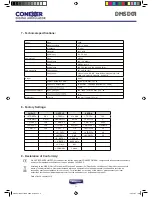
3 - Installation and menu structure

3.1 - Installation

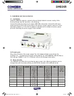
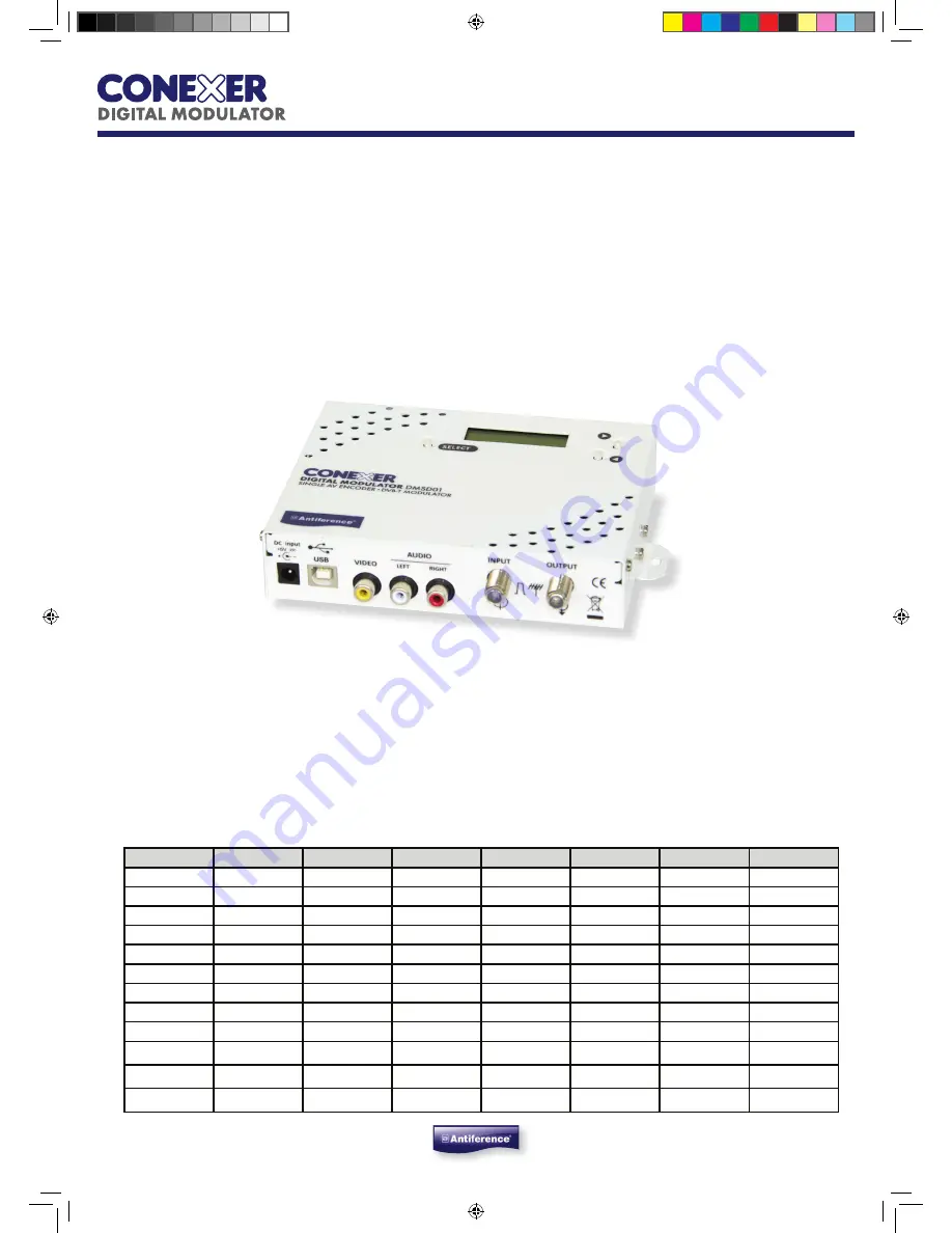
Install the DMSD01 against a wall using the wall fixing brackets to ensure cooling of the 

housing through natural convection. ( see drawing)

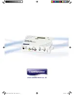
Connect the audio and video source using CVBS RCA connectors. Connect the RF input 

cable (if present) and the RF output cable. If the input is not used, please connect a 75 ohm 

terminating resistor to it. Once the modulator is installed and the cables connected, please 

proceed connecting the power supply to the modulator. 

3.2 Powering Up

Plug in the connector of the power supply. The LCD display will light up and shows the 

message “Init ...” followed by a bar graph, during starting  up of the DMSD01. After starting up 

the message “DMSD01’ and “V1.9’ (firmware version) are displayed alternating.

3.3 - Menu structure

The  DMSD01 has different menus allowing easy access to the different parameters and to 

change them when necessary. Below you will find the structure of the different menus.

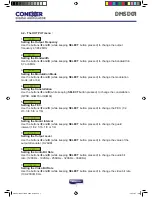
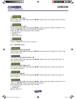
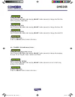
INPUT

OUTPUT

EXTRA

MISC.

<STDARD>

< FREQ >

<TS. ID>

<LANG.>

<FORMAT>

<BNDWDT>

<PRG.ID>

<RESET>

< LIGHT >

<  MODE  >

<NET ID>

<RETURN>

<CONTR.>

< CONST. >

<ONETID>

< SAT. >

< FEC  >

<NETWRK>

<RETURN>

<G. INT.>

<PMTPID>

<ATTEN.>

<VIDPID>

<A. RATE>

<AUDPID>

<V. RATE>

<RETURN>

<L.C.N.>

<CHANNL>

<RETURN>

5

DMSD01

DMSD01 MODULATOR USER GUIDE.indd   5

13/01/2014   18:05

Summary of Contents for DMSD01

Page 1: ...USER MANUAL DIGITAL MODULATOR DMSD01 AV TO DVB T ENCODER MODULATOR DMSD01 MODULATOR USER GUIDE indd 1 13 01 2014 18 05...

Page 2: ...Programming mode page 6 4 1 Description of the INPUT menu page 6 4 2 Description of the OUTPUT menu page 7 4 3 Description EXTRA menu page 8 4 4 Description menu MISC miscellaneous page 9 5 Programmi...

Page 3: ...ing Use only a damp cloth without solvents 1 5 Ventilation In order to assure an adequate air circulation and to prevent overheating the ventilation holes should not be obstructed The module may not b...

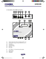
Page 4: ...MSD01 by PC C3 Video input C4 Audio left input C5 Audio right input C6 RF input C7 RF output A1 LCD display 1 x 8 characters with backlight T1 Select button T2 Right button T3 Left button OUTPUT AUDIO...

Page 5: ...ing Up Plug in the connector of the power supply The LCD display will light up and shows the message Init followed by a bar graph during starting up of the DMSD01 After starting up the message DMSD01...

Page 6: ...you can release the SELECT button 4 1 The INPUT menu 1 STDARD Setting the input standard Use the buttons t and u while keeping SELECT button pressed to change this option in PAL or NTSC 2 FORMAT Sett...

Page 7: ...tting the FEC Use the buttons t and u while keeping SELECT button pressed to change the FEC 1 2 2 3 3 4 5 6 or 7 8 6 G INT Setting the Guard Interval Use the buttons t and u while keeping SELECT butto...

Page 8: ...essed to change the number of the transport stream ID 2 PRG ID Setting the Programme ID Service ID Use the buttons t and u while keeping SELECT button pressed to change the number of the original netw...

Page 9: ...udio PID 4 RETURN To leave this menu Press the SELECT button to leave this menu 4 4 The MISC miscellaneous menu 1 LANG Setting the Language of the menus Use the buttons t and u while keeping SELECT bu...

Page 10: ...3 of this user manual can be modi ed by DMSDiFace 6 Using High Definition HD LCN In some systems you may want to broadcast a version of a programme in Standard Definition SD at the same time as High D...

Page 11: ...T ID 8442 CONTR 128 CONST 64QAM NETWRK NoName SAT 128 FEC 7 8 PMTPID 32 G INT 1 4 VIDPID 48 ATTEN 0 dB AUDPID 49 A RATE 384 Kb s V RATE 6000 Kb s L C N 801 CHANNL Chan A 11 DMSD01 9 Declaration of Con...

Page 12: ...www antiference co uk DMSD01 MODULATOR USER GUIDE indd 12 13 01 2014 18 06...

Reviews: