2 Overview
C58IB004EN-D
11
The connecting wires from the thermocouple and
the heating filament run within the black hose (sup-
ply hose) to the connection device described in
chapter 2.2.4 Connection Device
The housing of the DHS 1100 contains a bore hole
(A) for various connectors (B). The following con-
nectors are supplied with DHS 1100:
1
Blind plug
2
Feed-through adapter
3
Pressure relief valve
4
Hose connector
A blind plug (B.1) is provided for measurements un-
der vacuum.
The feed-through adapter (B.2) can be used togeth-
er with the hose connector (B.4) for additional gas
discharge.
The pressure relief valve (B.3) is a safety device that
opens if an overpressure of 0.35± 0.05 bar relative
pressure is generated in the dome.
TIP:
Additional information for replacing the con-
nectors can be found in chapter 6.5.2.3: Operation
under Vacuum.
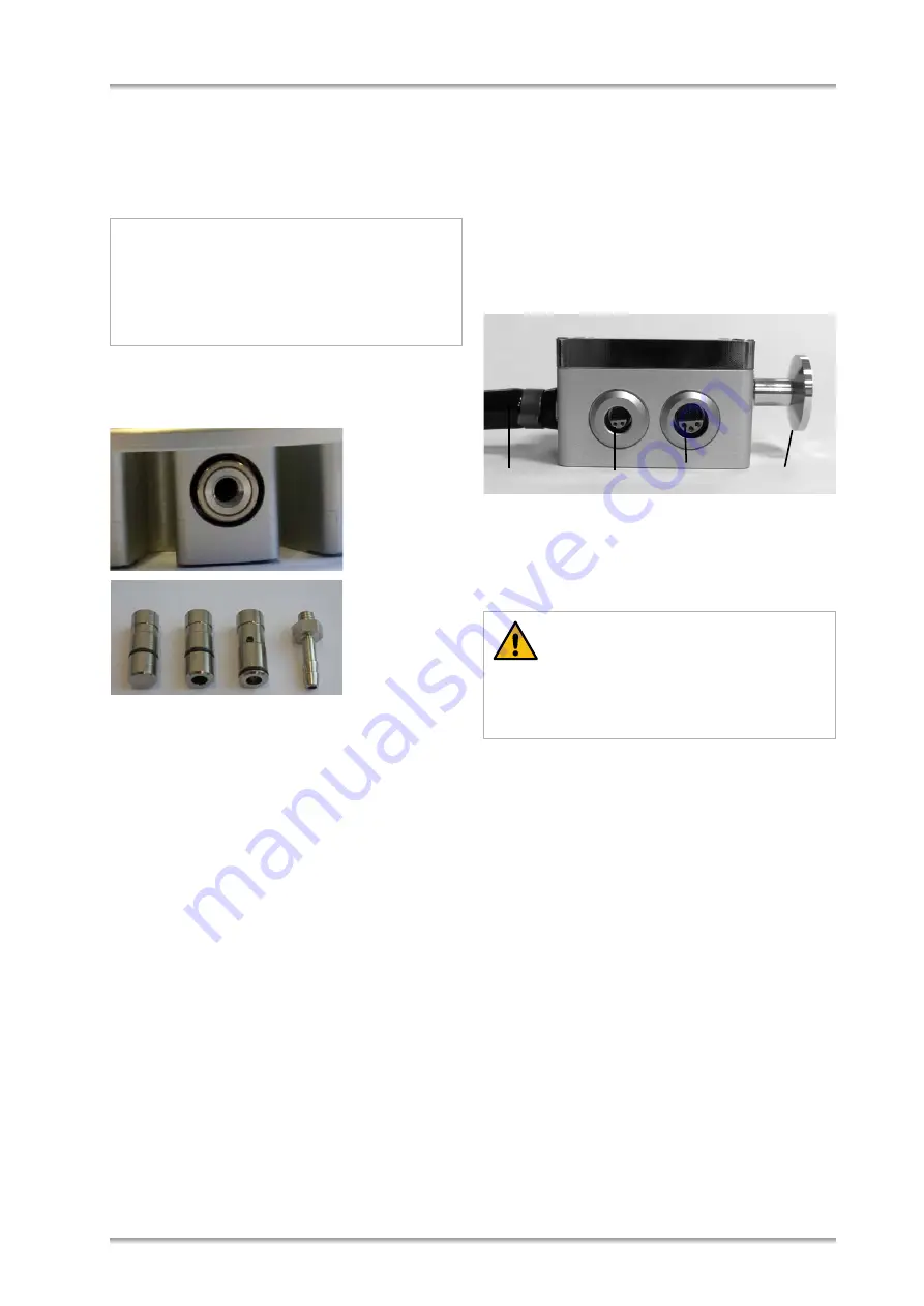
2.2.4 Connection Device
The connection device terminates the supply hose
of the DHS 1100, which contains the electrical wires
of the instrument and which is used to evacuate the
instrument or to fill it with gas. It is a vacuum-tight in-
terface box with connectors for the temperature
sensor and the heater inside the DHS 1100 and a
flange to connect a vacuum pump or the gas supply.
Fig. 5: Connection device
1
Supply hose with wires to thermocouple and heater
2
Connector for thermocouple (6 poles)
3
Connector for heating (4 poles)
4
Flange for gas supply / vacuum pump (DN16KF)
2.3 CCU 100 Combined Control Unit
CCU 100 is designed to control the sample plate
temperature in DHS 1100 and to guarantee safe op-
eration of the entire instrument. In order to reach
and maintain the desired sample temperature,
CCU 100 controls the resistance heater inside the
sample chamber and the compressed-air cooling.
CCU 100 can be operated manually by means of
the push - buttons on the front panel, or it can be re-
mote-controlled via a serial RS 232 interface.
The main parts of CCU 100 are the main board, the
micro controller for the temperature control and the
power module. The micro controller controls the
sample plate temperature based on the measured
temperature and the user defined target values. The
power module provides variable electrical power for
the heater inside DHS 1100, depending on the con-
trol signal from the micro controller.
NOTICE
Risk of damage
Do not disconnect the supply hose from the
DHS 1100 housing because the connecting
wires from the thermocouple and the heating fila-
ment can be damaged.
A
1
2
3
4
B
CAUTION
Place the connection device for gas/vacuum and
temperature control in a way that the hose is not
caught by any parts of the goniometer.
1
3
2
4


