3 Installation
C58IB004EN-D
15
3.3 Mounting the DHS 1100 on the
Goniometer
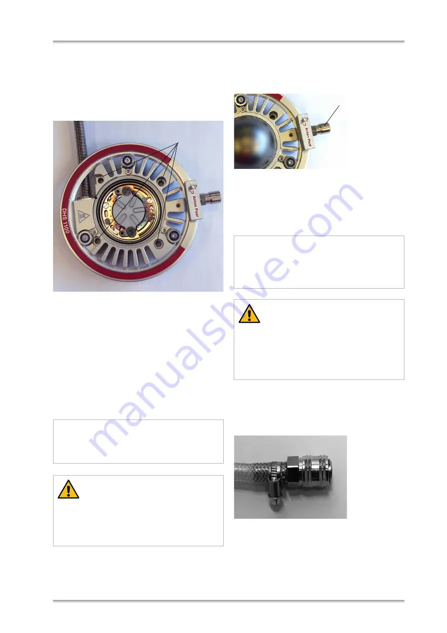
The DHS 1100 is mounted to the goniometer via the
four bore holes, as shown below.
For detailed information on the installation refer to
the
Instruction Manual
of your
Diffractometer
.
3.4 Installing the Compressed Air Cool-
ing
Cooling of the dome and the housing of the
DHS 1100 heating attachment is achieved by using
clean compressed-air. If no compressed-air supply
is available in the laboratory, a small compressor
can be used to generate the cooling air.
A black hose for the cooling air is supplied with the
DHS 1100. Install this supply hose as follows:
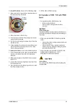
1. Connect the end of the hose inside the cabinet
to the appropriate quick coupling connector (1)
on the turnable ring of the DHS 1100.
2. Feed the air hose through the diffractometer
enclosure and connect it to the AIR OUTLET
connector on the rear panel of CCU 100.
Install the compressed-air cooling device on the
sample chamber as follows:
Connect the compressed-air supply to CCU 100:
1. Connect the female connector of the pneumatic
hose supplied with CCU 100 to the AIR INLET
connector on the rear panel of CCU 100.
2. Connect the
Air Service Unit
to the compressed-
air supply of the laboratory.
3. Connect the male connector of the pneumatic
hose to the outlet of the
air service unit
.
NOTICE
A special Air Service Unit can be used to clean
the cooling gas from dust and oil (refer to the ref-
erence guide C58IB002EN).
CAUTION
Do not connect the DHS 1100 directly to the
cooling air supply.
The cooling air must be supplied through the
CCU 100 Combined Control Unit.
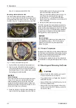
Bore holes for
mounting DHS 1100
NOTICE
When you dismount the compressed-air cooling
unit, push it upwards towards the DHS 1100
before you turn it to avoid damage to the locking
slit.
CAUTION
Risk of damage
Make sure that the compressed-air cooling unit
is securely locked in the connector before you
start to use the instrument. Gently try to pull it
downwards. It must be fixed on the connector.
1


