5 Operating CCU 100
20
C58IB004EN-D
5 Operating CCU 100
This chapter describes the operation of the
CCU 100 Combined Control Unit. CCU 100 can be
operated manually or by remote control.
Manual control is done with the keys on the front
panel of CCU 100. Manual operation is described in
Chapter 5.6 Manual Control of CCU 100
Remote control is done with a computer interfaced
to CCU 100 via the serial RS 232 interface and with
suitable software. See
for more infor-
mation.
CCU 100 can only store one target value for tem-
perature and heating/cooling rate at a time. Pro-
gramming temperature profiles into CCU 100 is not
possible on the controller itself. However, the deliv-
ered control software NAMBICON allows to pro-
gram a temperature profile (see the corresponding
software manual that was delivered with the instru-
ment).
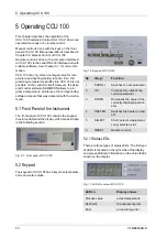
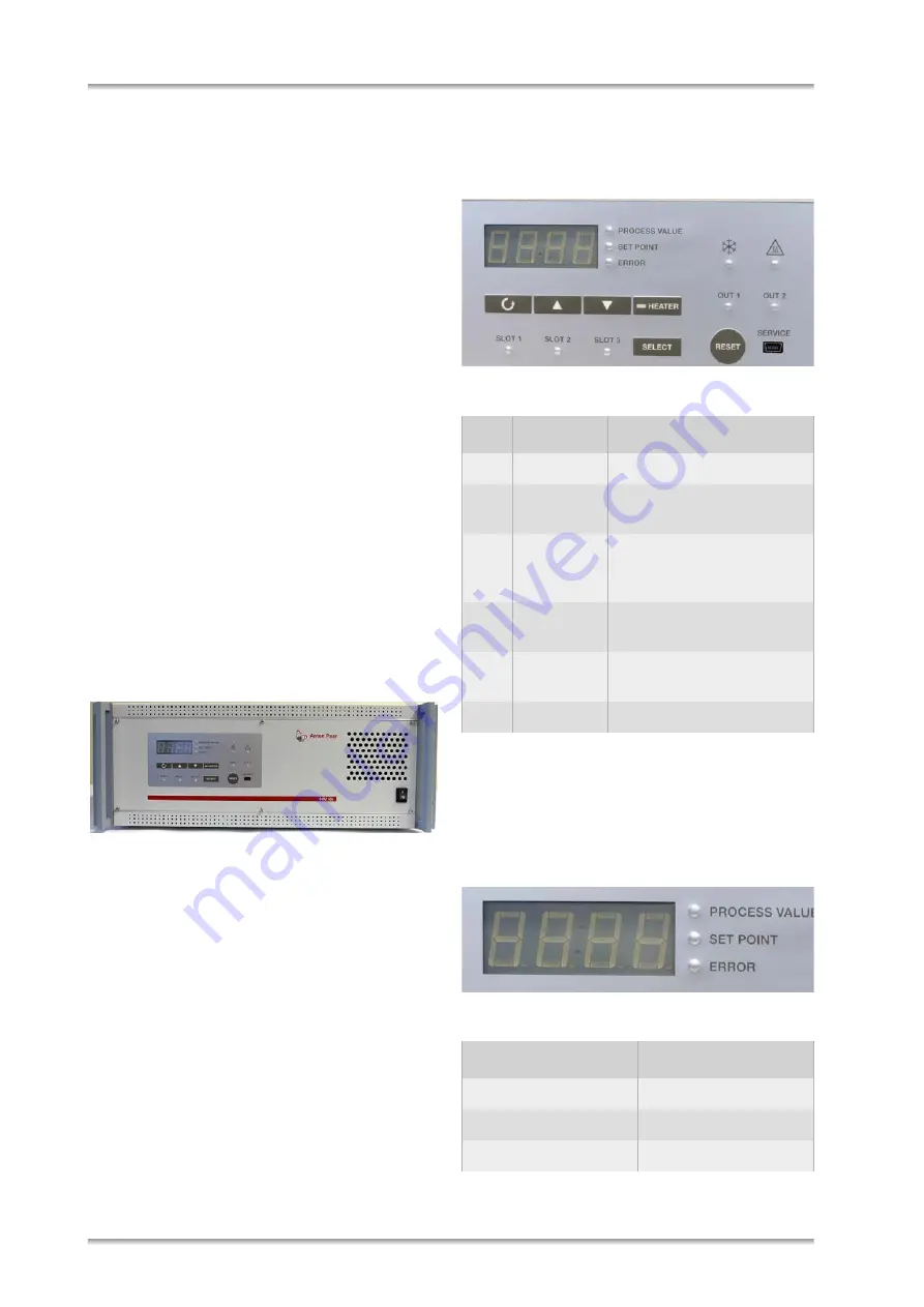
5.1 Front Panel of the Instrument
The front panel of CCU 100 contains the keypad,
the status LEDs and the display which are described
in the following section.
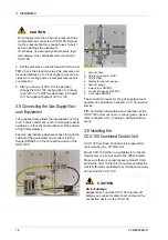
Fig. 5-1: Front panel of CCU 100
5.2 Keypad
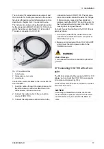
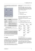
The keypad of CCU 100 has 6 keys to select param-
eters and enter values.
Fig. 10: Keypad of CCU 100
5.2.1
S
t
atus LEDs
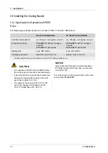
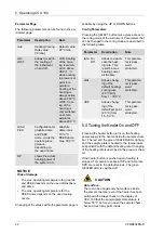
There are three types of status LEDs. The first type
of LEDs is located on the right side of the display
and gives additional information on the value that is
shown on the display.
Fig. 11: LEDs for value of CCU 100
No
<Key>
Function
1
SCROLL
Switches to next parameter
2
UP
Increase the value of the
current parameter
3
DOWN
Decreases the value of the
currently displayed param-
eter.
4
HEATER
Switches the heater on and
off.
5
SELECT
Short: selects a parameter.
Long: selects a slot.
6
RESET
Resets an error.
LED on
Display shows
Process value
actual temperature
Set Point
the actual set point
Error
an occurring error
1 2 3 4
5
6


