background image

UF SERIES WATER FILTRATION SYSTEM

9

P/N 1010827 Rev. D 04/06

INSTALLATION (continued)

PERMEATE LINE PLUMBING

To ensure the highest quality and safest water, it is 

recommended that a check valve (to prevent backflow) 

is installed in the water line after the permeate connec-

tion.  This helps prevent possible contamination of the 

filter system due to other equipment downstream.  The 

check valve (not supplied) should be mounted close to 

the system outlet and sized properly for the plumbing 

line.  Check with local codes for the proper specifica-

tion.

DRAIN LINE PLUMBING

The drain line is used to flush away the particle buildup 

when cleaning the filter.  The drain line must be able 

to support the flow rate when the system flushes.  The 

flow rate from the flush depends on the inlet water pres-

sure, inlet pipe size, and system selected.  It is recom-

mended that the drain line be as large as, or larger 

than, the inlet plumbing line.  The drain line should be 

as short as possible, sloping downward without kinks 

or loops.  Be sure that the drain used is not blocked or 

restricted.  

The filter system must be protected from possible back 

contamination by the installation of an air gap between 

the drain connection of the system and the drain 

(Figure 4).  This gap in the line, with no physical contact 

between the system and sewer, prevents contamination 

of the system in the event of a backed-up sewer.  

NOTE: Make sure that the end of the drain line is 

positioned and secured at least 2 inches above 

the drain so that the water flow is directed into the 

drain, without splashing.

FLUSHING AND STARTING THE SYSTEM 

To ensure that the highest quality water is produced 

from the system, the plumbing leading from the filter 

system must be flushed clear of all debris after the 

system is hooked up.  After making the connection 

to the outlet of the filter system, open a faucet or tap 

closest to the filter system, then slowly open the inlet 

water valve.  Allow the pipe to flush until all debris is 

removed.

The unit also must be flushed to remove air and the 

shipping/storage solution.  For maximum quality, the 

permeate water produced during the flushing procedure 

must be discarded.  Direct this permeate water to drain.  

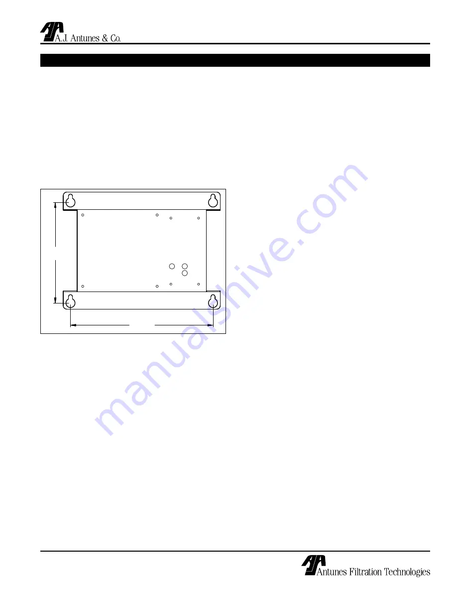
9 3/4"

(24.8 cm)

6 7/8"

(17.5 cm)

Figure 3. Mounting Bracket (Front View)

•  Install the system in a location that will allow for 

future service access.  

•  Mount the system on a wall using appropriate 

mounting hardware.  

•  Remember to consider the operating weight of 

the system when choosing mounting hardware.  

Depending on the type of wall the system is being 

mounted to, wall reinforcement may be necessary.

Mount the filtration unit using the Mounting Bracket 

(Figure 3) using 1/4” by 1” bolts or bolts of the metric 

equivalent.

INLET WATER PLUMBING

It is recommended that the inlet water plumbing line 

be 3/4” NPT or larger.  A shutoff valve (not supplied) 

should be installed in the line leading to the system.  

The valve should be mounted close to the system inlet 

and sized properly for the inlet plumbing line.  This 

valve will allow for easier servicing and future cartridge 

change-out. The system should only be connected to 

the cold water line.

To ensure that the highest quality water is produced 

from the system, the plumbing leading to the filter 

system must be flushed clear of all debris before the 

system is hooked up.  Before making the connection to 

the inlet of the filter system, hold a bucket or other con-

tainer at the inlet water line and slowly open the inlet 

water valved.  Allow the pipe to flush until all debris is 

removed.

Summary of Contents for UF-420 Series

Page 1: ...WATER FILTRATION SYSTEM UF 420 440 Series Owner s Manual P N 1010827 Rev D 04 06 MANUFACTURING NUMBERS 9700440 9700442 9700443 9700450 9700452 9700453 ...

Page 2: ...factured from the finest materials available and is assembled to AFT s strict quality standards This unit has been tested at the factory to ensure dependable trouble free operation Warranty Information Please read the full text of the Limited Warranty in this manual If the unit arrives damaged contact the carrier imme diately and file a damage claim with them Save all packing materials when filing...

Page 3: ...ning the unit WARNING GENERAL WARNING Indicates informa tion important to the proper operation of the equipment Failure to observe may result in damage to the equipment and or severe bodily injury or death WARNING ELECTRICAL WARNING Indicates infor mation relating to possible shock hazard Failure to observe may result in damage to the equipment and or severe bodily injury or death CAUTION GENERAL ...

Page 4: ...ontact with the membrane can cause irreversible damage to the membrane All pipes must be flushed clean before installing the filter All plastic parts of the filter system must be protected from sharp objects like knives sand paper or other tools Cutting or nicking a plastic part can weaken it and cause a leak Do not use abrasive cleansers on any plastic parts Protect from water hammer The system m...

Page 5: ...sh screen Recommended Permeate Tank Less than 300 GPD Greater than 300 GPD Flush Program Interval 6 hour Duration 15 seconds Flush Program Interval 1 hour Duration 15 seconds Less than 45 psi Greater than 1 NTU Required Inlet water strainer 150 micron 100 mesh screen Required Permeate Tank Any Flush Program Interval 1 hour Duration 15 seconds Greater than 45 psi Greater than 1 NTU Required Pressur...

Page 6: ...ce is properly grounded Model Voltage Watts Hertz UF 420 120 10 50 60 UF 440 230 10 50 60 Electrical Cord Plug Configurations Letter Code Description Configuration C H Commercial Cord Harmonized Cord H C CEE 7 7 16 Amp 250 VAC Assembly Only C F 5 15P 15 Amp 120 VAC Non Locking Assembly Only H K Chinese Australian 10 Amp 250 VAC Assembly only WHT BLK GRN Used in Model Designation Indicates that the...

Page 7: ...B Depth inches C Height inches Operating Weight w water lbs UF 420 6 1 16 14 7 8 33 7 8 30 UF 440 6 1 16 14 27 32 53 17 32 51 A B C Figure 1 Dimensions SPECIFICATIONS continued Components LED Display Program Button Power Cord Filter Cartridge Figure 2 Components Permeate Drain Inlet Strainer ...

Page 8: ...e sealant inside the pipe when making the connections Do not over tighten the connections It is recommend ed that plastic fittings be used when connecting to the INSTALLATION plastic connections of the system This will reduce the possibility of cracking the connections due to overtight ening If soldered plumbing is used do not apply heat to or near the filtration system The use of union O ring sea...

Page 9: ... system the plumbing leading from the filter system must be flushed clear of all debris after the system is hooked up After making the connection to the outlet of the filter system open a faucet or tap closest to the filter system then slowly open the inlet water valve Allow the pipe to flush until all debris is removed The unit also must be flushed to remove air and the shipping storage solution ...

Page 10: ...utes without water flow open the tap for 5 minutes to allow any trapped air to be flushed out 9 Close the tap Flushing is complete INSTALLATION continued SANITIZING THE SYSTEM AND LINES The plumbing must be sanitized to eliminate possible contamination that may have occurred during the instal lation process Chlorine bleach can be used to sanitize the plumbing The amount of bleach used depends on t...

Page 11: ...he UF Series is accomplished using two modes Flush Interval Fi on the LED display Flush Duration Fd on LED display During the Flush Interval mode water enters the inlet and flows through the filter element before exiting the Permeate outlet as usable product water After a cer tain period of time depending upon water quality the filter has to be cleaned This is accomplished through the Flush Durati...

Page 12: ...h Duration Mode Figure 9 Time Setting Fd Mode 55 Seconds Table A LED Display Settings Figure 7 Time Setting Fi Mode 22 Hours Figure 6 LED Display for Flush Interval Mode SETTING FLUSH DURATION FD 2 When Fd is displayed press and release the Start button to view the current setting Figure 8 3 To make a program change press and hold the Start button to scroll through settings release the Start butto...

Page 13: ...terval Mode Manual Flushing NOTE Manual flushing only works when unit is in Flush Interval Mode Fi While the unit is in Flush Interval Mode decimal point flashing hold the start button down for 6 7 seconds until the LED displays FL Figure 14 Continue hold ing the button down to keep the drain open Drain will remain open for as long as start button is depressed FL will flash on LED Releasing the bu...

Page 14: ... cap and screw the cap onto the cartridge Tighten with strap wrench as necessary 14 Follow the Flushing and Starting the System and Sanitizing the System and Lines procedures in the Installation section of this manual to complete the cartridge change System sanitization Over time and use the plumbing downstream from the system may require sanitization It is recommended that the system and downstre...

Page 15: ... in pipes Sanitize plumbing Water conditions changed Consider installing taste and odor filtration Broken capillary in Filter Cartridge Replace Filter Cartridge Flush runs continuously Drain Valve stuck open Replace rebuild the Drain Valve Controller sending continuous signal to valve Replace the controller Flush runs too long Program duration set too long Re program the unit to flush for a shorte...

Page 16: ...or Mfg s 9700442 9700452 13 0504034 Clamp Filter 4 1 14 0504033 Mounting Bracket 4 1 15 2090122 Cartridge Filter 4 x 20 For 1 Mfg s 9700440 and 9700442 2090123 Cartridge Filter 4 x 40 For 1 Mfg s 9700450 and 9700452 16 0011911 Connector End Cap 4 2 17 2180177 Cap End 2 2 18 0200224 O Ring 4 2 19 2190134 Tee Strainer 3 4 NPT 1 20 2090133 Screen Tee Strainer 3 4 NPT 1 21 0200223 Gasket Tee Strainer ...

Page 17: ...UF SERIES WATER FILTRATION SYSTEM 17 P N 1010827 Rev D 04 06 REPLACEMENT PARTS UF 420 440 continued 14 6 13 5 26 1 2 15 17 17 25 23 19 20 21 22 28 3 4 8 18 24 16 16 18 7 32 29 30 31 9 10 29 29 34 33 ...

Page 18: ...on Technologies reserves the right to make changes in design or add any improvements on any product The right is always reserved to modify equipment because of factors beyond our control and government regulations Changes to update equipment do not constitute a warranty charge 3 If shipment is damaged in transit the purchaser should make a claim directly upon the carrier Careful inspection should ...

Reviews: