background image

P/N 1010455 Rev. K 10/20

®

Miracle Steamer

Owner’s Manual

Model MS-250/255

Original Instructions 

www.antunes.com

READY

Manufacturing Numbers:

9100430, 9100431, 9100435, 9100436, 

9100437, 9100438, 9100460, 9100462, 

9100466, 9100467, 9100468, 9100933, 

9100936

Summary of Contents for 9100430

Page 1: ... 20 Miracle Steamer Owner s Manual Model MS 250 255 Original Instructions www antunes com READY Manufacturing Numbers 9100430 9100431 9100435 9100436 9100437 9100438 9100460 9100462 9100466 9100467 9100468 9100933 9100936 ...

Page 2: ...or reference If the unit changes ownership this manual must accompany it In Case of Damage If the unit arrives damaged file a claim with the carrier immediately Save all packing materials when filing a claim Freight damage claims are the respon sibility of the purchaser and are not covered under warranty Website www antunes com Service Technical Assistance If you experience any problems with the i...

Page 3: ...holes or cracks This damage is permanent and is not covered by warranty y Always use a soft damp cloth for cleaning Rinse with clear water and wipe dry When required always rub in the direction of metal polish lines y Routine cleaning should be performed daily with soap and water y Do not clean unit or components in a dishwasher unless specifically specified in the cleaning instructions y Do not c...

Page 4: ...437 230 3300 14 4 50 60 6 20P 20 Amp 250 VAC Non Locking MS 250 9100438 230 3300 14 4 50 60 CEE 7 7 16 Amp 250 Volt MS 255 9100460 230 3300 14 4 50 60 6 20P 20 Amp 250 VAC Non Locking MS 255 9100462 120 1800 15 0 50 60 NEMA 5 15P 15 Amp 120 Volt MS 255 9100466 230 3300 14 4 50 60 6 20P 20 Amp 250 VAC Non Locking MS 255 9100467 Saudi Arabia 230 3300 14 4 50 60 IEC 309 16 Amp 250 VAC Pin Sleeve Asse...

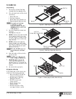
Page 5: ...air dry NOTE MFG No 9100933 does not use the Drip Pan or Steam Vent 6 Wipe all surfaces of the unit with a hot damp cloth NOTE Do NOT use a dripping wet cloth Wring out before use 7 MS 250 Models Assemble the Guard and Mounting Bolt to the Spatula Figure 3 Then install the Wire Trivet into the side slots on the Spatula 8 Re install all removed parts Equipment Setup When placing the unit into servi...

Page 6: ...r is controlled by a normally closed NC sole noid valve located inside the Steamer s electrical housing 1 Turn off the water valve not sup plied that supplies water to the unit Figure 4 2 Connect the 1 4 6 5 mm I D Flexible Tubing to the outlet side of the Water Pressure Regulator and secure using the Worm Clamp Figure 4 NOTE A Water Pressure Regulator must first be installed Figure 4 Failure to d...

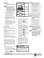
Page 7: ...ime in minutes press or to change the time Figure 6 Item B 4 Press and release again and press or to change the Total Cycle Time in seconds Figure 6 Item C 5 To change the SHO factory settings make sure the control is in PROGRAM mode then press and hold both and simultaneously for 1 2 seconds and release SHO will be displayed Figure 6 Item D 6 Press and release and then press or to change the SHO ...

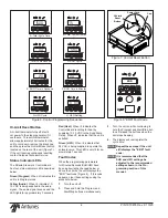
Page 8: ...e Yellow Audio When lit indicates 10 15 VDC is being supplied to the audio signal The audio signal sounds and the LED lights for approximately 3 seconds Red Heat When lit indicates the Control Board is calling for heat by supplying 10 15 VDC to the Solid State Relay When off indicates that the unit is satisfied Green H2O When lit indicates that 24 VAC is being supplied to operate the solenoid valv...

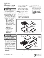
Page 9: ...kg cm2 or 138 172 kPa If not adjust the pressure as described in the Installation section of this manual 3 Check the rear water Quick Discon nect Fitting and Hose Clamp for leakage Tighten clamps or replace parts if needed Maintenance Drip Pan Except Mfg No 9100933 Drawer Liner with Rollers Drawer Top Cover Steam Vent except Mfg No 9100933 Figure 9 Daily Cleaning MS 250 Figure 10 Daily Cleaning MS...

Page 10: ...nge or a dry towel remove the delimer solution from the Generator surface then rinse with clean water NOTE To ensure proper steaming characteristics some calcium mineral deposits must be present on the Generator surface If during cleaning the surface does become free of calcium mineral deposits add plain tap water to the surface and allow it to boil off If necessary repeat this process to formulat...

Page 11: ... the clear plastic Strainer Cup and carefully remove the Mesh Screen 2 At the sink gently flush all of the ac cumulated debris from the Strainer Cup and Mesh Screen Be espe cially careful not to damage the Mesh Screen 3 Carefully place the Mesh Screen into its seat at the bottom of the Strainer Cup and confirm that the or ange O ring is properly seated in its place before screwing the Strainer Cup...

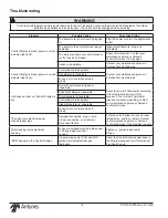
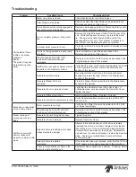
Page 12: ... of this manual If the Hi Limit Thermostat requires continuous resetting contact your maintenance person or Antunes Technical Service Solid State Relay is inoperable Thermocouple is inoperable Control Board is inoperable Steam Generator is inoperable Loose burnt or broken wires in circuit The unit s main electrical panel circuit breaker trips Damaged receptacle plug or cord a loose connection or a...

Page 13: ...r steaming Refer to the Maintenance section of this manual Generator Steam Ports are restricted Clean the Steam Ports as described in the Maintenance section of this manual Generator Cover is warped or loose Verify that the Generator Cover Wing Nut is tight If noticeable steam escapes around the Generator Cover replace the cover Generator Diffuser is missing Install Generator Diffuser or replace i...

Page 14: ...Tube 4 1 2 Lg 1 48 300P102 Nut Speed U 8 32 2 49 304P105 Nut Hex KEPS 4 40 Zinc 4 50 306P101 Nut Hex 6 32 2 51 306P105 Screw Machine 6 32 x 1 2 2 52 306P123 Screw Machine 6 32 x 7 8 2 53 306P130 Nut Hex KEPS 6 32 2 54 306P134 Screw Machine 6 32 x 3 8 3 55 308P103 Screw Machine 8 32 x 1 4 6 57 308P105 Screw Machine 8 32 x 1 2 4 58 308P120 Screw Machine 8 32 x 5 8 sltrshd 4 59 308P124 Screw Machine ...

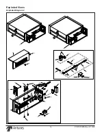
Page 15: ...55 Rev K 10 20 15 RE AD Y 64 17 15 18 20 74 36 22 66 65 6 7 8 10 12 13 24 62 94 35 70 57 54 54 54 42 41 89 81 88 93 81 80 85 79 84 83 82 86 87 85 90 95 98 99 74 36 90 95 21 11 7a Exploded Views Exploded Diagram 1 ...

Page 16: ... P N 1010455 Rev K 10 20 16 READY 22 55 READY 72 49 48 67 50 71 51 57 55 68 69 19 55 25 59 60 27 29 32 33 23 55 28 46 30 5 55 46 37 2 97 READY 26 34 1 Exploded Views Exploded Diagram 2 ...

Page 17: ...4 Long 1 3 2030125 Tubing 1 4 I D PVC BRD 12 Long 1 4 2040150 Elbow Male Nylon 1 4 Barb x 3 8 NPT 2 5 0503615 Bracket Manifold Mtg 1 6 2190129 Nipple 1 4 NPT x 1 4 NPT 1 7 7000333 Strainer 1 4 FPT 1 8 2080118 Quick Disconnect 1 8 NPT 1 9 2190113 Manifold 1 10 211P104 Clamp Ear Med 4 11 2040151 Nipple Hex 3 8 x 1 4 NPT Nylon 1 12 7000306 Gauge Water Pressure 1 13 2170113 Regulator Pressure 1 Item N...

Page 18: ...N 1010455 Rev K 10 20 18 Wiring Diagram NOTE For 208 240 VAC units the two primary coils are wired in series with one another For 120 VAC units the two primary coils are wired in parallel with one another ...

Page 19: ... P N 1010455 Rev K 10 20 19 Notes ...

Page 20: ...olenoid valves It does not cover water pressure problems or failures resulting from improper incorrect voltage supply This warranty does not cover Travel Time Mileage in excess of 2 hours 100 miles 160 km round trip from the nearest authorized service agency 2 Antunes reserves the right to make changes in design or add any improvements on any product The right is always reserved to modify equipmen...

Reviews: