background image

®

P/N 1011596 Rev. A 05/21

14

Sanitizing the Plumbing

The plumbing from the RO System 

must be sanitized to eliminate possible 

contamination that may have occurred 

during the installation process. 

One ounce (30 ml) of liquid chlorine bleach 

(regular bleach, unscented 5.25 % - 6 % 

sodium hypochlorite) or Kay-5 sanitizer 

solution (Sodium Dichloro-s-Triazinetrione 

Dihydrate, 6%) or equivalent can be used 

to sanitize the plumbing. 
The Kay-5 sanitizer solution is made by 

dissolving a 1 oz. packet of Kay-5 powder 

in 2 oz. (60 ml) of clean warm water. This 

can be done by removing 1 inch from the 

top of the Kay-5 packet and adding the 2 

oz. of warm water to the packet. Mix with 

a coffee stirrer to dissolve. When added to 

the plumbing from the RO System, this will 

create a 60-100 ppm chlorine solution. 

NOTE:

 Follow the handling and safety 

instructions supplied with the 

sanitizer.

1. 

Follow the steps in the 

Rinsing the 

RO System

 section of this manual. 

2. 

Turn off the water to the system.

3. 

Close the Tank valve.

4. 

Allow the system and plumbing 

to drain by opening the line 

downstream to the RO System.

5. 

Disconnect the line to the 

equipment being served at the Tee 

fitting and pour the sanitizer into 

the line using a cup or funnel. Be 

careful not to spill the sanitizer onto 

clothing or skin. 

6. 

Reattach the line to the Tee fitting.

7. 

Slowly turn on the Tank valve and 

allow water to flow through the line 

and out to the equipment.

8. 

Let stand without water flow for at 

least 15 minutes to allow time for 

the pipes to be sanitized.

9. 

After 15 minutes without water flow, 

open the line at the equipment and 

allow water and sanitizer to flow 

until the presence of sanitizer is 

gone.

10. 

Reconnect all lines and turn on 

water to the RO. The system is now 

ready for use.

Maintenance

Replacing the RO Cartridge

NOTE:

 Always install a new Carbon 

cartridge after replacing the RO 

Cartridge.

1. 

Turn off water to the system by 

closing the feed water valve and 

unplug the system power cord from 

the outlet.

2. 

Close the tank valve.

3. 

Depressurize the system.

4. 

Pull out the tube which is inserted 

into the RO housing’s inlet.

5. 

Using the supplied wrench, unscrew 

the RO housing end cap and 

remove the old RO cartridge.

NOTE:

 Water may drain from the 

system and cartridge as it is 

removed. 

6. 

Unwrap the new cartridge and 

record the serial number of the new 

cartridge.

7. 

Check to make sure that all 

the O-rings in the end caps are 

lubricated with a food grade silicone 

lubricant. 

8. 

Insert the RO membrane into the 

housing. The RO membrane must 

be installed with the brine seal on 

the right side, nearest to the RO 

membrane housing inlet. 

NOTE:

 Make sure the cartridge is 

installed with the brine seal to 

the right (RO housing inlet), if 

not, the system will not work 

properly.

9. 

Reattach the RO membrane 

housing end cap. Reinstall the 

tube that was removed previously 

by pushing it into the RO housing 

inlet. Make sure the tubing is fully 

engaged in the fitting.

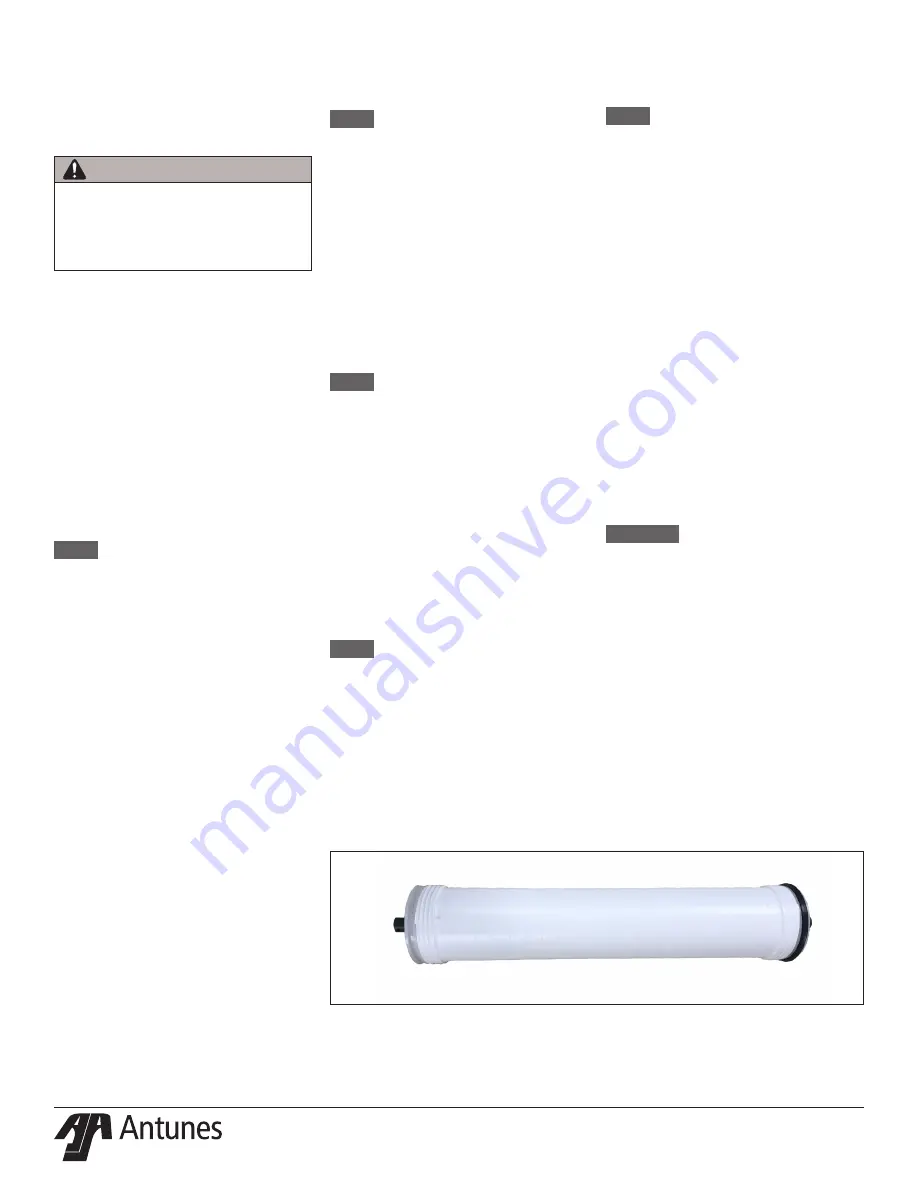
Figure 13. 

RO Cartridge

NOTE:

 Failure to fully engage the 

tubing could result in leaks and 

flooding.

10. 

Turn on the feed water and plug the 

system power cord into the outlet. 

Air and water should flow out of the 

brine (drain) tubing and permeate 

tubing.

11. 

Observe the system for leaks, 

especially at the newly replaced 

cartridge.

12. 

The system should be flushed as 

described in the installation section 

under RINSING THE RO SYSTEM.

13. 

When flushing is complete, open the 

tank valve.

14. 

Record the next change date of the 

RO Cartridge.

UV System (Option) 

Maintenance

The UV system requires periodic 

maintenance in order to function properly.

WARNING:

 The UV light given off by 

the UV bulb can cause serious 

burns to unprotected eyes 

and skin. Do NOT perform any 

maintenance tasks with the bulb 

plugged in and powered on.

Pay attention to the following guidelines 

when working with the UV light:


y

  Never look directly at an 

illuminated UV lamp


y

Always unplug the UV unit before 

performing any work on the UV 

bulb or disinfection system


y

Never operate the UV bulb 

outside of the UV housing

WARNING

Do not pour sanitizer into the system 

inlet! The RO membrane can be 

destroyed if exposed to sanitizer. Only 

the downstream plumbing from the 

system should be sanitized.

Summary of Contents for 9710141

Page 1: ... Rev A 05 21 Reverse Osmosis System Owner s Manual Models AQ RO 400 AQ RO 600 Manufacturing Numbers 9710141 9710142 9710143 www antunes com CAUTION Read all instructions before using the unit Original Instructions ...

Page 2: ...ee Fill in the information in the next column and have it handy when calling for assistance The serial number is on the specification plate located on the system Purchased From Date of Purchase Model Number Serial Number Mfg Number Suggested replacement period for the RO Cartridge is 1 year IMPORTANT This equipment is to be installed to comply with the basic plumbing code of the Building Officials...

Page 3: ...esult Protect from direct sunlight or other UV sources Avoid long term exposure to direct sunlight or other UV sources The RO should be stored in a dark location Protect from high temperatures or abrupt variation in temperature The maximum operating temperature is 100 F 38 C Avoid abrupt variations in temperature Any temperature variation should be made slowly Protect from rough handling or droppi...

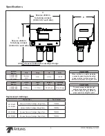
Page 4: ... AQ RO 400 Reverse Osmosis Cartridge Single Pack 7002303 AQ RO 600 Reverse Osmosis Cartridge Single Pack 7002304 Replacement Cartridges CAUTION When installed on metallic plumbing a properly sized electrical bonding jumper must be installed across the inlet and outlet pipes serving this unit CAUTION To ensure proper installation wall anchors for unit must be rated for AT LEAST 60lbs 30 kg or MORE ...

Page 5: ...ex 5 5 Iron Hydrogen Sulfide or Manganese 0 0 Nominal Capacity 400 600 Membrane performance after 24 hours at 77 F 25 C 500 ppm TDS and 70 psig Membrane performance after 24 hours at 77 F 25 C 500 ppm TDS and 80 psig Performance Claims for Percent Reduction Substance Minimum Reduction Total Dissolved Solids TDS 94 NOTE Do not use with water that is microbiologically unsafe or of unknown quality wi...

Page 6: ... P N 1011596 Rev A 05 21 6 Water Mark Listing ...

Page 7: ...ut the system will not flush This will cause the RO membrane to plug prematurely and reduce the life of the RO System y Tank Full Mode When the tank is full no water runs out of the drain line CAUTION Stopping the drain flow can cause the Filter to plug prematurely and may reduce the life of the filter Consult the factory for more information Figure 1 System Components Figure 2 Water Connections T...

Page 8: ...s and supplies are suggested to help with the installation y Screwdriver y Adjustable Wrenches y Drill with Bits y Level y Tape Measure y Pipe Dope or Thread Seal Tape y Two Gallon Bucket y Fresh Unscented Liquid Chlorine Bleach y Pipe Wrenches y Hose or pipe for drain line Mounting the System The RO System comes with a Mounting Bracket for the system When mounting the system pay attention to the ...

Page 9: ...lips beside the filtration system with the appropriate mounting hardware NOTE Pay attention to the distance between the two clips it is recommended that the distance be approximately 2 3 the length of the UV light 2 Take out the UV bulb and the power supply from the box 3 Insert the bulb into the UV housing Only keep the end of the bulb out 4 Connect the bulb and the power supply 5 Attach the powe...

Page 10: ...e and slope downwards without any kinks or loops y The drain line plumbing must be positioned and secured at least 2 inches above the drain Figure 7 This air gap protects the system from contamination in the event of a backed up drain y The drain used must not be blocked or restricted y The drain used must be as large or larger than the drain line plumbing y The drain line from the system should b...

Page 11: ...e starts to calculate When the running time is activated on the RO membrane the RO membrane lifetime is based on the calendar time and running time which value is reached first Items Status Filters F1 Prefilter a 10 100 Life Always on b 0 10 Life Symbol Flickering c 0 Life Symbol Off Maintenance IL on Buzz 3 times min F2 Carbon F3 RO Membrane Status PROCESSING a Letter on flickering system flushin...

Page 12: ... not already installed install the Pre filters and RO Membrane The white sediment prefilter must be installed in the left prefilter housing closest to the water inlet The carbon prefilter must be installed in the right prefilter housing after the sediment prefilter The RO membrane must be installed with the brine seal on the right nearest to the RO membrane housing inlet It should only be inserted...

Page 13: ... and let water into the system 6 Plug the power cord into an outlet The pump will come on and air in the pre filters and RO membrane will come out Wait 5 10 minutes until all air has been removed 7 Adjust the brine control valve so that the pressure gauge is 80 psi Opening the brine control valve increases the brine flow rate and lowers the membrane pressure and product water flow rate 8 Continue ...

Page 14: ...e tank valve 3 Depressurize the system 4 Pull out the tube which is inserted into the RO housing s inlet 5 Using the supplied wrench unscrew the RO housing end cap and remove the old RO cartridge NOTE Water may drain from the system and cartridge as it is removed 6 Unwrap the new cartridge and record the serial number of the new cartridge 7 Check to make sure that all the O rings in the end caps a...

Page 15: ...ord the date the cartridges where changed and the next change date Replacing the Sediment Prefilter Cartridge NOTE Always install a new Sediment Prefilter Cartridge when replacing the Carbon cartridge 1 Turn off the water to the system by closing the feed water valve 2 Close the tank valve 3 Open a valve on the line to the store to depressurize the system 4 Unscrew the bowl and remove the old sedi...

Page 16: ...lies required Air Pressure Gauge 5 40 psi range 0 3 2 7 bar with tire valve Schrader Valve connection Source of compressed air manual bicycle tire pump or air compressor CAUTION Air pre charge should be checked and adjusted under zero system pressure The system must be depressurized before checking the tank pre Charge Do NOT adjust the tank air pre charge with the system under pressure CAUTION Be ...

Page 17: ...n cartridges Storage shipping solution not completely rinsed out of the system Rinse the system for a longer period of time replace carbon cartridges Biological growth in pipes Sanitize plumbing Water conditions changed Consider installing additional filtration Broken membrane in RO Cartridge Replace RO Cartridge Flush runs continuously Tank pressure switch stuck open Replace tank pressure switch ...

Page 18: ...arts Exploded View 73 32 32 1 43 51 72 62 21 21 13 24 19 24 13 21 41 41 61 4 23 56 21 57 56 37 18 13 36 13 37 18 46 45 53 53 35 40 54 16 22 48 52 14 16 13 17 27 25 16 13 2 49 63 6 20 31 50 29 30 15 16 26 55 60 21 59 19 20 13 25 40 54 55 38 38 ...

Page 19: ...MPOUND 4 35 2170201 PRESSURE GAUGE PANEL MOUNTED 1 36 2170212 BLEND VALVE 3 8 TUBE PANEL MOUNTED 1 37 2180495 FILTER BOWL 2 38 2180495 FILTER HEAD 2 39 2180495 FILTER O RING 2 40 2180772 MOUNTING CLIP RO HSG 2 41 2180779 HOUSING BOWL AND HEAD RO 1 42 2180823 GLUE BOX RO CONTROLLER 1 43 2180824 SUPPORT FRAME RO CONTROLLER 1 44 2180825 PLASTIC CLIP M4 x 6 3mm 4 45 2190251 ADAPTOR TUBE TO 1 2 NPT 1 4...

Page 20: ...ure F Feed Pressure psig Product Flowrate ml min Drain Flowrate ml min Percent Recovery Product TDS ppm Feed TDS ppm Percent Rejection Date Date Date Changed Sediment Next Sediment Change Changed Carbon Next Carbon Change Changed RO Next RO Change ...

Page 21: ... P N 1011596 Rev A 05 21 21 NOTES ...

Page 22: ...nvolved in moving adjacent objects to gain access to the Equipment 2 Antunes reserves the right to make changes in design or add any improvements on any product The right is always reserved to modify equipment because of factors beyond our control and government regulations Changes to update equipment do not constitute a warranty charge 3 If shipment is damaged in transit the purchaser should make...

Reviews: