background image

P/N 1011306 Rev. D   12/17

6

MAINTENANCE

CAUTION

Chlorides or phosphates in cleaning agents 

(e.g. bleach, degreasers or detergents) 

could cause permanent damage to stain-

less steel equipment.  The damage is 

usually in the form of discoloration, dulling 

of metal  surface finish, pits, voids, holes 

or cracks. This damage is permanent and 

NOT covered by warranty.  The following 

tips are recommended for maintenance 

of your stainless steel equipment:


y

Always use soft, damp cloth 

for cleaning, rinse with clear 

water and wipe dry.  When 

required, always rub in direction 

of metal polish lines.


y

Routine cleaning should be 

done daily using soap, ammonia 

detergent and water.


y

Stains and spots should be 

removed using a vinegar solution.


y

Finger marks and smears should 

be removed using soap and water.


y

Hard water spots should be 

removed using a vinegar solution.

WARNING

Turn the power off, unplug the power cord, 

and allow the unit to cool down before 

performing any service or maintenance.

WARNING

Do NOT use abrasive cleansers or ma-

terials.  The use of these may cause 

damage to the stainless steel finish.

Daily Cleaning

The unit requires a minimum amount of 

maintenance. To ensure proper operation, 

clean the unit at the end of each serving 

day.

1.  Turn both the Light and Heat rocker 

switches to the off position.

2.  Unplug the power cord from the 

electrical outlet and allow the unit 

to cool to room temperature before 

proceeding.

3.  Remove any product tray and wash 

in soap and water. Then rinse and 

wipe dry.

4.  Clean glass surfaces, inside and out, 

with an approved glass cleaner.

5.  Wipe all non-glass surfaces of the 

unit with a clean damp towel and 

allow to air dry.

OPERATIONS AND 

PROGRAMMING

The DCH-800 andDCH-1000 is designed to 

temporarily slow the cooling of food.

NOTE:

  This unit has an adjustable 

temperature range of 150-165° F 

(66-74° C).

NOTE:

   The Setpoint temperature is 

the desired cabinet tempera-

ture setting.  When the Temp 

UP button is pressed and held 

(and provided that the unit is 

up to temperature), the actual 

cabinet temperature is displayed.  

When the button is released, 

the Setpoint temperature is 

displayed.

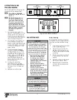
1.  Turn the Heat rocker switch ON 

(Figure 2).  The display flashes “LO” to 

indicate that the unit is heating up.  

After 20-30 minutes (when the unit 

is up to temperature), the display will 

show the setpoint temperature.

2.  Turn the Light rocker switch to turn 

on the LED lights and illuminate 

product. Use the Light Dimmer Knob 

to adjust the brightness of the lights. 

1 is the lowest setting and 10 is the 

highest setting.

3.  To adjust the setpoint tempera-

ture, press and hold the Temp Up 

and Temp Down buttons until the 

display begins to flash.  Release the 

buttons.  Then, press the Temp Up 

or Temp Down buttons to raise or 

lower the setpoint temperature.  

Release when the display shows the 

desired temperature.

4.  To change the display from 

Fahrenheit to Celsius and back, 

press and hold the Temp Scale but-

ton (Figure 3) for 2-3 seconds and 

release.

5.  Load product into the display.

Light

Rocker Switch

Light

Dimmer Knob

Heat

Rocker Switch

Figure 2. DCH-1000 Turning on Heat and Lights

TEMP

UP

TEMP

DOWN

TEMP

SCALE

F

C

O

O

Figure 2. DCH-1000 Control Panel

Summary of Contents for DCH-1000

Page 1: ...P N 1011306 Rev D 12 17 Heated Display Cabinet owner s manual Models DCH 500 DCH 800 DCH 1000 Manufacturing Numbers 9500640 9500650 9500720 www antunes com ...

Page 2: ...r damage as result of improper use y y Installation of electrical service y y Normal maintenance as outlined in this manual y y Malfunction resulting from improper maintenance y y Damage caused by abuse or careless handling y y Damage from moisture into electrical components y y Damage from tampering with removal of or changing any preset control or safety device SERVICE TECHNICAL ASSISTANCE If yo...

Page 3: ...rating and performing maintenance on this unit y y If the supply cord is damaged it must be replaced by the manufacturer or its service agent or a similarly qualified person in order to avoid a hazard y y Do not modify the power supply cord plug If it does not fit the outlet have a proper outlet installed by a qualified electrician y y Do not use an extension cord with this appliance y y Electrica...

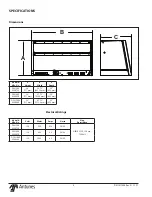
Page 4: ...6 50 60 NEMA 5 15P 15 Amp 120 Volt DCH 800 9500650 120 800 6 6 50 60 DCH 1000 9500640 120 1000 8 3 50 60 Electrical Ratings Dimensions Model Mfg No A Height B Width C Depth DCH 500 9500720 28 711 mm 23 75 603 25 mm 25 635 mm DCH 800 9500650 28 711 mm 37 75 958 8 mm 25 635 mm DCH 1000 9500640 28 711 mm 47 75 1212 8 mm 25 635 mm ...

Page 5: ...rface Ensure that the line voltage corresponds to the stated voltage on the unit specification label Ensure the power to the unit is turned off before plugging in the power cord CAUTION All electrical connections must be in accordance with local electrical codes and any other applicable codes WARNING y y ELECTRICAL SHOCK HAZARD Failure to follow the instructions in this manual could result in seri...

Page 6: ...ter Then rinse and wipe dry 4 Clean glass surfaces inside and out with an approved glass cleaner 5 Wipe all non glass surfaces of the unit with a clean damp towel and allow to air dry OPERATIONS AND PROGRAMMING The DCH 800 andDCH 1000 is designed to temporarily slow the cooling of food NOTE This unit has an adjustable temperature range of 150 165 F 66 74 C NOTE The Setpoint temperature is the desi...

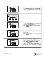
Page 7: ... exceeds the setpoint temperature or if the thermistor has shorted NOTE The thermistor should be 100k ohm 2 at room temperature OPEN flashes if the thermistor is OPEN or disconnected The unit will not call for heat NOTE The thermistor should be 100k ohms 2 at room temperature PO In 120 VAC units this code flashes if the supply voltage is below 100 VAC or above 135 VAC In 220 240 VAC units this cod...

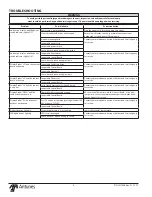
Page 8: ...e Relay Contact your maintenance person or Authorized Service Agency for service Inoperable Control Board Inoperable Heater s Loose burnt broken wiring in circuit Display flashes HI and the cabinet does not heat up Inoperable Thermistor Contact your maintenance person or Authorized Service Agency for service Inoperable control Board Display flashes HI and the cabinet is very hot Solid State Relay ...

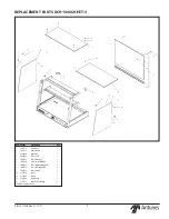
Page 9: ... 0900320 Front Glass 1 4 5040282 Rail 48 68 LG 1 5 7001732 Glass Shelf Kit 24 1 6 7001380 Side Glass Kit 0900319 2 7 2000253 Glass Shelf Mounting Hdwe 2 8 7001435 Glass Shelf Support Kit 2 9 7001438 Corner Bracket 2 10 215P410 Spacer 1 11 325P207 Washer 1 12 210P360 Thumb Screw 1 13 215P152 Nylon Push in Bearing 1 Available in packages of ten ...

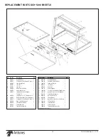
Page 10: ...ermostat Hi Limit Kit 1 15 7001478 Terminal Block Kit 1 16 0013258 Control Panel Assembly 1 Item Part No Description Qty 17 0022270 Heat SinkWeldment 1 20 7001148 Transformer 120VAC 12VAC 1 21 7000370 Solid State Relay Kit 1 22 0400251 Strain Relief 1 23 0700463 Power Cord 1 24 7001718 Power Supply Kit 1 25 308P203 Screw 8 32 X 3 8With Int ToothWasher 1 26 308P199 Nut Hex Keps 8 32 S S Cti Ifn0037...

Page 11: ...ion Qty 1 7001714 Top Glass Kit 36 1 3 0900326 Front Glass Assy 1 4 5040284 36 Frame Hinge 1 5 Middle Shelf waiting on kit 1 6 7001380 Side Glass Kit 0900319 2 7 7001435 Glass Shelf Support Kit 2 9 7001438 Corner Bracket 2 10 215P410 Spacer 1 11 325P207 Washer 1 12 210P360 Thumb Screw 1 13 215P152 Nylon Push in Bearing 1 Available in packages of ten ...

Page 12: ...Limit Kit 1 15 7001478 Terminal Block Kit 1 Item Part No Description Qty 16 7000345 Control Board Kit 1 17 0022132 Heat Sink BracketWeldment 1 20 7001148 Transformer 120VAC 12VAC 1 21 7000370 Solid State Relay Kit 1 22 0400251 Strain Relief 1 23 0700463 Power Cord 1 24 7001718 Power Supply Kit 1 25 308P203 Screw 8 32 X 3 8With Int ToothWasher 1 26 308P199 Nut Hex Keps 8 32 S S Cti Ifn00374 1 27 00...

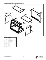
Page 13: ...1 2 7001869 Front Glass kit 1 3 0900320 Front Glass 1 4 5040282 Rail 48 68 LG 1 5 7001870 Glass Shelf Kit 1 6 7001380 Side Glass Kit 0900319 2 7 7001435 Glass Shelf Support Kit 2 8 7001438 Corner Bracket 2 9 210P360 Thumb Screw 1 REPLACEMENT PARTS DCH 1000 SHEET 1 3 2 4 1 5 8 7 4 6 9 ...

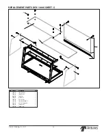
Page 14: ...l Board Kit 1 Item Part No Description Qty 17 0022132 Heat SinkWeldment 1 20 7001148 Transformer 120VAC 12VAC 1 21 7000370 Solid State Relay Kit 1 22 0400251 Strain Relief 1 23 0700463 Power Cord 1 24 7001718 Power Supply Kit 1 25 308P203 Screw 8 32 X 3 8With Int ToothWasher 1 26 308P199 Nut Hex Keps 8 32 S S Cti Ifn00374 1 27 0022097 Control PanelWeldment 1 28 0400138 Nut Lock Conduit 1 2 1 29 05...

Page 15: ...P N 1011306 Rev D 12 17 15 NOTES ...

Page 16: ...P N 1011306 Rev D 12 17 16 ...

Page 17: ...warranty does not cover water contamination problems such as foreign material in water lines or inside solenoid valves It does not cover water pressure problems or failures resulting from improper incorrect voltage supply This warranty does not cover Travel Time Mileage in excess of 2 hours 100 miles 160 km round trip from the nearest authorized service agency 2 Roundup reserves the right to make ...

Reviews: