1007 & 3007 ROLL GROOVER
20
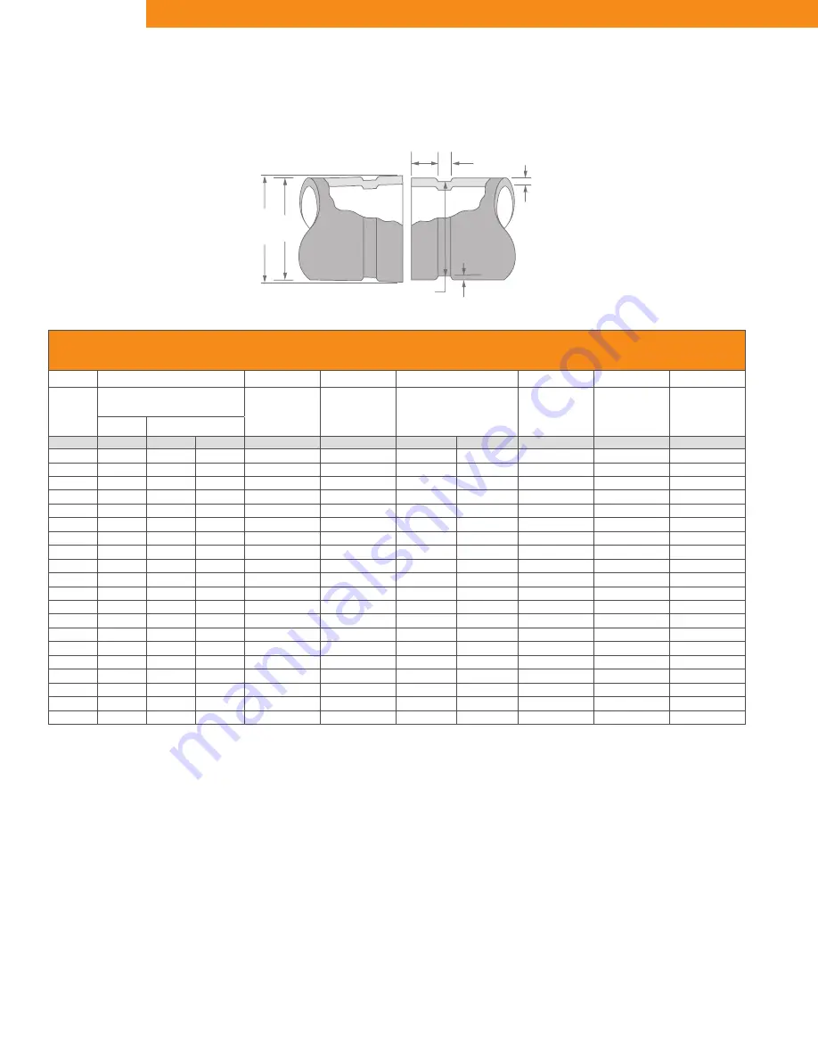
COLUMN 1 - Nominal IPS Pipe size
COLUMN 2 - IPS outside diameter
COLUMN 3 - Gasket seat must be free from
scores, seams, chips, rust or scale
which may interfere with proper
sealing of the gasket. Gasket
seat width (Dimension A) is to be
measured from the pipe end to the
vertical flank in the groove wall.
COLUMN 4 - Groove width (Dimension B) is to be
measured between vertical flank of
the groove size walls.
COLUMN 5 - The groove must be of uniform
depth around the entire pipe cir-
cumference. (See column 6).
COLUMN 6 - Groove depth: for reference only.
Groove must conform to the groove
diameter “C” listed in column 5.
COLUMN 7 - Minimum allowable wall thickness
which may be roll grooved.
COLUMN 8 - Maximum allowable pipe end flare
diameter. Measured at the most
extreme pipe end diameter of the
gasket seat area.
GRUVLOK STANDARD ROLL GROOVE SPECIFICATIONS FOR STEEL & OTHER IPS SIZE PIPE
-1-
-2-
-3-
-4-
-5-
-6-
-7-
-8-
Nominal
IPS
Pipe Size
Pipe OD
Gasket Seat
Groove Width
Groove Diameter
Groove Depth
Min. Allow.
Wall Thickness
“T”
Max.
Flare
Diameter
“A”
“B”
“C”
“D”
Actual
Tolerance
±0.030/ ±0.76 ±0.030/ ±0.76
Actual
Tol. +0.000
(Ref. Only)
In./DN(mm)
In./mm
+In./mm
-In./mm
In./mm
In./mm
In./mm
-In./mm
In./mm
In./mm
In./mm
2
2.375
+0.024
-0.024
0.625
0.344
2.250
-0.015
0.063
0.065
2.480
50
60.3
+0.61
-0.61
15.88
8.74
57.15
-0.38
1.60
1.7
63.0
2
1
⁄
2
2.875
+0.029
-0.029
0.625
0.344
2.720
-0.018
0.078
0.083
2.980
65
73.0
+0.74
-0.74
15.88
8.74
69.09
-0.46
1.98
2.1
75.7
3
3.500
+0.035
-0.031
0.625
0.344
3.344
-0.018
0.078
0.083
3.600
80
88.9
+0.89
-0.79
15.88
8.74
84.94
-0.46
1.98
2.1
91.4
3
1
⁄
2
4.000
+0.040
-0.031
0.625
0.344
3.834
-0.020
0.083
0.083
4.100
90
101.6
+1.02
-0.79
15.88
8.74
97.38
-0.51
2.11
2.1
104.1
4
4.500
+0.045
-0.031
0.625
0.344
4.334
-0.020
0.083
0.083
4.600
100
114.3
+1.14
-0.79
15.88
8.74
110.08
-0.51
2.11
2.1
116.8
5
5.563
+0.056
-0.031
0.625
0.344
5.395
-0.022
0.084
0.109
5.660
125
141.3
+1.42
-0.79
15.88
8.74
137.03
-0.56
2.13
2.8
143.8
6
6.625
+0.063
-0.031
0.625
0.344
6.455
-0.022
0.085
0.109
6.730
150
168.3
+1.60
-0.79
15.88
8.74
163.96
-0.56
2.16
2.8
170.9
8
8.625
+0.063
-0.031
0.750
0.469
8.441
-0.025
0.092
0.109
8.800
200
219.1
+1.60
-0.79
19.05
11.91
214.40
-0.64
2.34
2.8
223.5
10
10.750
+0.063
-0.031
0.750
0.469
10.562
-0.027
0.094
0.134
10.920
250
273.1
+1.60
-0.79
19.05
11.91
268.27
-0.69
2.39
3.4
277.4
12
12.750
+0.063
-0.031
0.750
0.469
12.531
-0.030
0.109
0.156
12.920
300
323.9
+1.60
-0.79
19.05
11.91
318.29
-0.76
2.77
4.0
328.2
T
B
D
C
OD
Flare
A
OUT OF ROUNDNESS:
Difference between
maximum O.D. and minimum O.D. measured
at 90° must not exceed total O.D. tolerance
listed (reference column 2).
FOR IPS PIPE,
the maximum allowable tolerance
from square cut ends is 0.03" for 2" thru 3
1
⁄
2
";
0.045" for 4" thru 6"; and 0.060" for sizes 8"
and above measured from a true square line.
BEVELED-END PIPE
in conformance with ANSI
B16.25 (37
1
⁄
2
°) is acceptable, however square cut
is preferred.
GROOVE SPECIFICATION - STEEL


