3.
Cover the
Silica gel Backing Plate
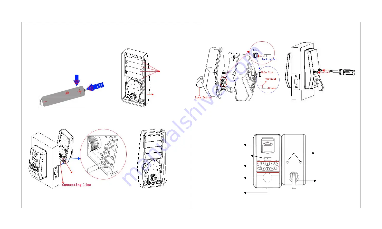
onto the
Rear panel Assembly
, turn the
Lock Button
to make the
Hole Slot
vertical to the ground, and insert
Locking Bar
into the
Hole Slot
, as shown in
Figure 19
. In this case, when you
turn the
Lock Button
, the bolt can sprung out or back automatically.
4.
Push the
Rear panel Assembly
ahead to ensure that it can cover the whole
Back Lining Plate
. Install screws and
fix them using a screwdriver. As shown in
Figure 20
.
.
Ⅸ
Use Instructions
1. Panel Description
Ⅶ
. Install the Batteries
1.
Prepare four AA batteries. You are advised to use new batteries with the same brand.
2.
Put batteries into the
Rear panel Assembly
properly. As shown in
Figure 161
and
162
:
Ⅷ
. Install the Rear panel Assembly
1.
Pull the
Connecting Wire
into the
Wire Hole
of the
Rear panel Assembly
. As shown in
Figure 17
:
2.
Tuck up the
Connecting Wire
for further
Rear panel Assembly
installation. As shown in
Figure 18
.
7
8
①
Fingerprint Collector
②
Start
key/
LED Status indicator
③
Number keys
⑤
Emergency Power Interface
④
Key Hole
⑥
Screw Hole
⑦
Lock Button
Figure 161
Figure 162
Figure 17
Figure 18
Figure 19
Figure 20
Wire Hole
Rear panel Assembly
AA batteries


