57
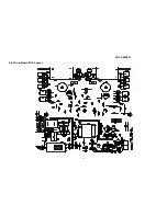
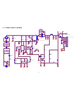
10-2 Power board
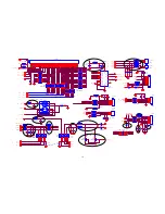
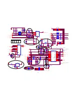
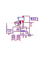
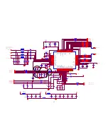
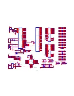
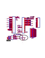
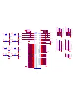
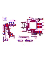
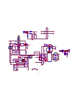
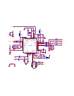
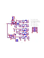
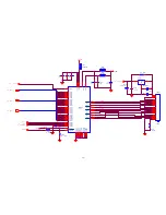
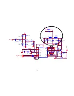
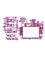
11. SCHEMATIC DIAGRAM (CIRCUIT)
11-1. MAIN BOARD SCHEMATIC DIAGRAM
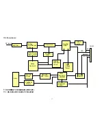
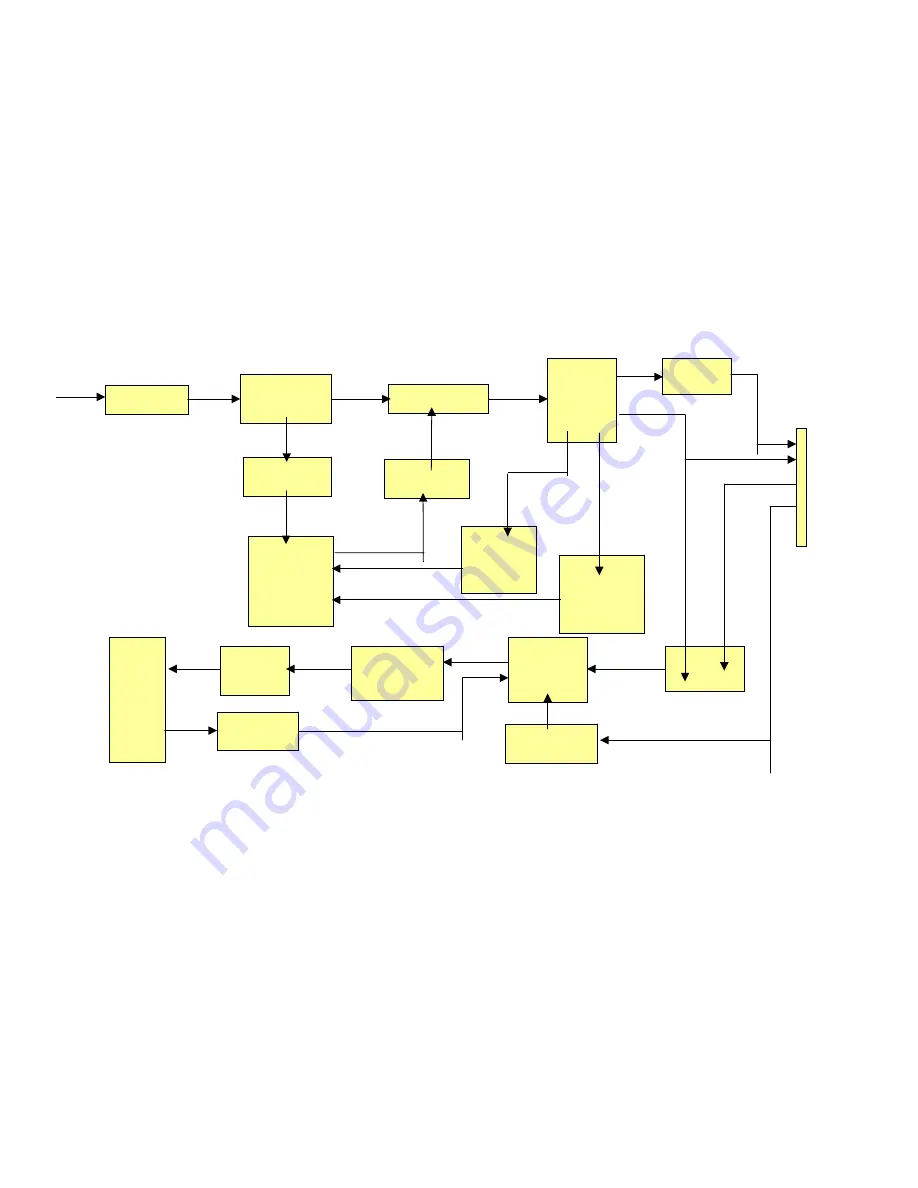
EMI filter
Bridge
Rectifier and
Filter
Start Circuit
R906, R907
PWM
Control IC
Transformer
Over
Voltage
Protect
MOSFET
Q901
Rectifier
CMOS
Voltage
Feedback
Circuit
AC input
5V
12V
ON/OFF
Control
PWM
Control IC
LM339M
Feedback
Circuit
ROYER
Circuit
MOSFET
Q201, Q211
Lamp
ON/OFF
BL ADJ
CN902
IC101,
Q101
Brightness
Control
Summary of Contents for A20E221 Series
Page 13: ...AOC A20E221 13 The color temp is for you to adjust the color temperature to one you prefer ...
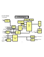
Page 15: ...AOC A20E221 15 4 2 Main Board Power Circuit 4 3 Remote Control Block ...
Page 16: ...AOC A20E221 16 4 4 Key Board Control Block ...
Page 17: ...AOC A20E221 17 4 5 PC Control Block ...
Page 18: ...AOC A20E221 18 ...
Page 19: ...AOC A20E221 19 4 6 Audio Control Block ...
Page 23: ...AOC A20E221 23 ...
Page 24: ...AOC A20E221 24 ...
Page 25: ...AOC A20E221 25 ...
Page 26: ...AOC A20E221 26 7 MECHANICAL OF CABINET FRONT DIS ASSEMBLY ...
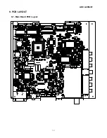
Page 54: ...AOC A20E221 54 9 PCB LAYOUT 9 1 Main Board PCB Layout ...


