background image

20" LCD Color Monitor                                         AOC e2040S


52 


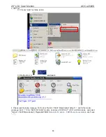
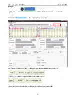
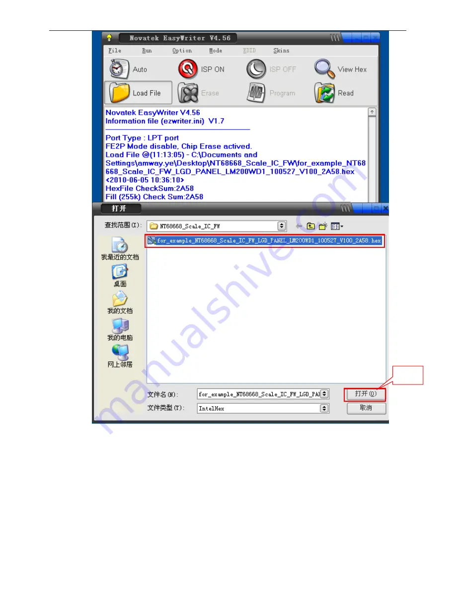
Click “Auto” to upgrade F/W. Appear the dialog box as follow. 

open 

Summary of Contents for e2040S

Page 1: ...ory Preset Display Modes 9 5 Panel Specification 10 5 1 Display Characteristics 10 5 2 Optical Characteristics 10 5 3 Parameter guide line for CCFL Inverter 10 6 Block Diagram 11 Table Of Contents 1 Revision List 2 1 Monitor Specification 4 2 LCD Monitor Description 5 3 Operation Instruction 7 3 1 General Instructions 7 3 2 Control Button 7 3 3 Adjusting the Picture 7 4 Input Output Specification ...

Page 2: ...aracteristics might create shock fire or other hazards Under no circumstances should the original design be modified or altered without written permission from AOC AOC assumes no liability express or implied arising out of any unauthorized modification of design Servicer assumes all liability FOR PRODUCTS CONTAINING LASER DANGER Invisible laser radiations when open AVOID DIRECT EXPOSURE TO BEAM CA...

Page 3: ...20 LCD Color Monitor AOC e2040S 3 Revision List Version Date Revision History Remark A00 Sep 28 2010 Initial release TAAGNRNEWWA1NNE TAAGNT2CWWA12NE ...

Page 4: ...20 LCD Color Monitor AOC e2040S 4 1 Monitor Specification ...

Page 5: ...ontrol logic brightness control logic and DDC The power part will provide AC to DC Inverter voltage to drive the backlight of panel and the main board chips each voltage AC IN 100V 240V Monitor Block Diagram Converter board Flat Panel and LED backlight Main Board RS232 Connector For white balance adjustment in factory mode LED Drive Video signal DDC HOST Computer Key Board Adapter ...

Page 6: ...20 LCD Color Monitor AOC e2040S 6 View and Dimension ...

Page 7: ...r to navigate through the functions Once the desired function is highlighted press the MENU button to activate sub menu Once the desired function is highlighted press MENU button to activate it 3 Press or to change the settings of the selected function Press or to select another function in sub menu Press AUTO to exit If you want to adjust any other function repeat steps 2 3 4 OSD Lock Function To...

Page 8: ...20 LCD Color Monitor AOC e2040S 8 Luminance ...

Page 9: ...20 LCD Color Monitor AOC e2040S 9 ...

Page 10: ...20 LCD Color Monitor AOC e2040S 10 Image Setup ...

Page 11: ...20 LCD Color Monitor AOC e2040S 11 Color Temperature ...

Page 12: ...20 LCD Color Monitor AOC e2040S 12 ...

Page 13: ...20 LCD Color Monitor AOC e2040S 13 Color Boost ...

Page 14: ...20 LCD Color Monitor AOC e2040S 14 Picture Boost ...

Page 15: ...20 LCD Color Monitor AOC e2040S 15 OSD Setup ...

Page 16: ...20 LCD Color Monitor AOC e2040S 16 Extra ...

Page 17: ...20 LCD Color Monitor AOC e2040S 17 Reset ...

Page 18: ...20 LCD Color Monitor AOC e2040S 18 Exit LED Indicator ...

Page 19: ...20 LCD Color Monitor AOC e2040S 19 4 Input Output Specification 4 1 Input Signal Connector D SUB connector ...

Page 20: ...20 LCD Color Monitor AOC e2040S 20 4 2 Factory Preset Display Modes ...

Page 21: ...de LED backlight system The matrix employs a Si Thin Film Transistor as the active element It is a transmissive type display operating in the normally white mode It has a 20 0 inch diagonally measured active display area with HD resolution 900 vertical by 1600 horizontal pixel array Each pixel is divided into Red Green and Blue sub pixels or dots which are arranged in vertical stripes ...

Page 22: ...20 LCD Color Monitor AOC e2040S 22 4 3 2 Optical Characteristics ...

Page 23: ... is displayed and fV is the frame frequency 2 The current is specified at the maximum current pattern 3 Permissive power ripple should be measured under VCC 5 0V 25 C fV frame frequency 75Hz condition and At that time we recommend the bandwidth configuration of oscilloscope is to be under 20MHz 4 The duration of rush current is about 5ms and rising time of power Input is 500us 20 Back Light Unit T...

Page 24: ...20 LCD Color Monitor AOC e2040S 24 5 Block Diagram 5 1 Software Flow Chart 1 2 N Y 5 Y N 10 Y N 12 Y N 7 Y N 6 4 3 8 9 14 11 13 Y N 15 Y N 16 17 19 Y N 18 ...

Page 25: ...n on the LED and set it to green color Scalar initialize 10 In standby mode 11 Update the lifetime of back light 12 Check the analog port are they re any signals coming 13 Does the scalar send out an interrupt request 14 Wake up the scalar 15 Are there any signals coming from analog port 16 Display No connection Check Signal Cable message And go into standby mode after the message disappear 17 Pro...

Page 26: ... 5 2 Electrical Block Diagram 5 2 1 Scalar Board FLASH MEMORY Pm25LD020C U402 Scalar NT68668AFG Include MCU ADC OSD etc U401 LCD Interface CN301 D Sub Connector CN101 EEPROM AT24C02BN U101 Crystal 12MHZ X401 Key Control Interface CN401 ...

Page 27: ...801 PWM Control MP3389EF U801 14 5V MOSFET Q806 DIM ENA L801 LED CN802 EMI filter Start Resistor R906 R934 PWM Control LD7750GS IC901 Transformer T901 AC input 12V 3A Bridge Rectifier and Filter Rectifier diodes Photo coupler IC902 Regulator IC903 Power Switch Q901 ...

Page 28: ...CN 5 U106 AOZ8105CI I O1 1 GND 2 I O2 3 I O3 4 VDD 5 I O4 6 DDC1_SCL 5 DDC1_SDA 5 DDC1_SDA VGA_B U105 AOZ8105CI I O1 1 GND 2 I O2 3 I O3 4 VDD 5 I O4 6 DDC_WP 5 U107 AOZ8105CI I O1 1 GND 2 I O2 3 I O3 4 VDD 5 I O4 6 FB102 0R05 1 10W 1 2 FB103 0R05 1 10W 1 2 FB101 0R05 1 10W 1 2 11 30 2009 11 30 2009 11 30 2009 DDC_WP 5 CN102 JACK DAT2 1 DAT2 2 2 4shield 3 DAT4 4 DAT4 5 DDC SCL 6 DDC SDA 7 VSYNC 8 ...

Page 29: ... 2009 R308 NC 10K1 16W CN301 CONN 2 4 6 8 10 12 14 16 18 20 22 24 26 28 30 32 1 3 5 7 9 11 13 15 17 19 21 23 25 27 29 31 PANEL_VCC Q302 LMBT3904LT1G R304 22K 1 16W R305 10K 5 1 16W CMVCC1 C302 22UF 16V U301 NC AO4411 S 1 S 2 S 3 G 4 D 8 D 7 D 6 D 5 LVACKM RXEC LVBCKM RXOC RXE2 LVA2M RXE1 LVA1M RXO3 LVB3M RXE0 LVA0M RXO0 LVB0M RXE3 LVA3M RXO1 LVB1M LVB2M RXO2 OEM MODEL Size Rev Date Sheet of TPV MO...

Page 30: ...EN SW 1 EN 2 COMP 3 FB 4 GND 5 FREQ 6 VIN 7 BST 8 Thermal Pad 9 VCC3 3 11 30 2009 U701 VI 3 VO 2 GND 1 C723 10uF 25V C712 100nF 25V C719 100nF 25V CMVCC1 CN702 CONN 1 2 3 4 5 6 7 8 9 10 11 12 D707 SR34 1 2 D708 SR34 1 2 C717 100N 16V 2010 1 13 2010 1 13 2010 1 13 2010 1 13 BKLT EN FB702 BEAD 1 2 12V 12V 6 BKLT VBRI R707 0R05 1 10W BKLT EN R708 NC 0R05 1 10W 5 BKLT VBRI R702 10K 5 1 16W R703 10K 5 ...

Page 31: ... VCC1 8 4 119 ADC_VAA FB401 0R05OHM1 8W 115 52 adj_BACKLIGHT CMVCC1 DSUB_R 2 DSUB_G 2 DSUB_G 2 DSUB_B 2 DSUB_SOG 2 DSUB_V 2 DSUB_B 2 DSUB_H 2 LED_GRN BLUE DDC1_SDA 2 LED_ORANGE DDC1_SCL 2 RX2P 2 RX2N 2 RX1P 2 RX1N 2 PS_DISTANCE C428 47pF 50V VCC3 3 CMVCC1 R436 1K 1 16W R437 1K 1 16W KEY1 KEY2 RX0P 2 RX0N 2 RXCP 2 RXCN 2 DDC2_SDA 2 R413 10K 5 1 16W DET_CABLE 2 R412 10K 5 1 16W PPWR_ON 3 SPI_CE SPI_...

Page 32: ... Pad 璶 TOP and Button常璶Τ R608 R611 R612 with audio NC POWER ON HI C627 NC 2009 12 14 2009 12 3 R618 10K 5 1 16W 2010 1 13 POWER OFF 2009 12 3 DEL C624 C625 2009 12 3 C626 1UF16V MUTE C627 1nF 50V C624 220P 50V OUT L C625 220P 50V C611 1UF16V OUT R MUTE R621 6 8K 1 1 16W C619 10U 10V FB604 120 OHM 1 2 OUT L FB601 120 OHM 1 2 AINR C616 10U 10V FB603 120 OHM 1 2 C605 1N 50V R622 1 24K 1 C613 1UF16V C...

Page 33: ...CN901 SOCKET 1 2 3 BD901 KBP306G 05 2 1 3 4 R901 1 MOHM 5 1 4W R902 1 MOHM 5 1 4W C903 0 47UF R940 220 OHM 1 10W C908 2N2 500V L902 14mH 1 4 2 3 L903 0 8uH R918 20K 1 10W 5 C920 1U 25V L901 0 45mH 1 4 2 3 C918 680UF 25V R941 1R5 1 8W 5 R916 11 5KOHM 1 1 8W C907 82uF 450V R911 2KOHM 1 10W R912 1K 1 10W R905 10K OHM 5 1 8W C910 100N 50V IC902 PC123X2YFZOF 1 2 4 3 IC903 KIA431A AT P C900 0 001uF 250V...

Page 34: ...20 LCD Color Monitor AOC e2040S 34 Converter 715G4082P01000004S ...

Page 35: ...20 LCD Color Monitor AOC e2040S 35 7 PCB Layout 7 1 Main Board 715G4002M01000004S ...

Page 36: ...20 LCD Color Monitor AOC e2040S 36 7 2 Power Board Adapter 715G3980P02000003S ...

Page 37: ...20 LCD Color Monitor AOC e2040S 37 Converter 715G4082P01000004S ...

Page 38: ...20 LCD Color Monitor AOC e2040S 38 7 3 Key Board 715G4014K01000004C ...

Page 39: ...C e2040S 39 8 Maintainability 8 1 Equipments and Tools Requirement 1 Voltmeter 2 Oscilloscope 3 Pattern Generator 4 DDC Tool with an IBM Compatible Computer 5 Alignment Tool 6 LCD Color Analyzer 7 Service Manual 8 User Manual ...

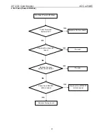
Page 40: ...heck power cable is tightened Check Power On Off is On Re plug the power cable Replace main board and check connections Check the LED indicate is OK Check the AC power Replace the converter board OK NG OK NG NG Turn on the Power On Off switch Replace key board and check connections NG ...

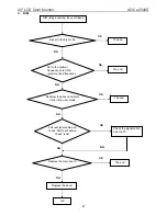
Page 41: ...deo Power LED Blue Press the power button is OK Check the LVDS FFC cable or panel The end NG OK OK NG Replace the main board Replace the converter board Replace the LVDS FFC cable or panel NG The end Replace the key board NG OK Replace the main board and connection OK ...

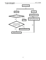
Page 42: ...r Reset in factory mode Set to the optimal frequency select the recommended frequency Pull out signal cable and check Self Test Feature Check is ok Check the signal cable and the PC Readjust the phase and pixel clock in the user mode Replace the main board Replace the panel NG NG NG OK NG NG OK The end OK NG ...

Page 43: ... Miss color Color shift Replace the signal cable Pull out the signal cable and check the screen color display is normal The end Replace the signal cable or PC Reset the factory mode In the user mode set the color settings until customer satisfy Replace the main board NG OK NG OK NG ...

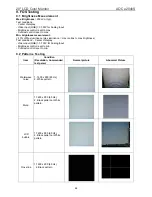
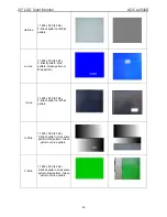
Page 44: ...luminance max contrast max brightness Test conditions Center of display Video input RGB 0 700V for Analog Input Brightness control is set to min Contrast control is set to min 9 2 Patterns Testing Item Condition Resolution Commended test paten Normal picture Abnormal Picture Waterwave noise 1 1600 x 900 60 Hz 2 White pattern Mura 1 1600 x 900 60 Hz 2 Black pattern or White pattern LCD bubble 1 160...

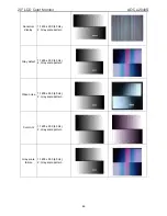
Page 45: ...2 Black pattern Red pattern Green pattern or Blue pattern V Line 1 1600 x 900 60 Hz 2 Black pattern or White pattern H Strip 1 1600 x 900 60 Hz 2 Black pattern Gray scale pattern Red pattern Green pattern or blue pattern V Strip 1 1600 x 900 60 Hz 2 Black pattern Gray scale pattern Red pattern Green pattern or blue pattern ...

Page 46: ...1 1600 x 900 60 Hz 2 Gray scale pattern Gray defect 1 1600 x 900 60 Hz 2 Gray scale pattern Video noise 1 1600 x 900 60 Hz 2 Gray scale pattern Color tint 1 1600 x 900 60 Hz 2 Gray scale pattern Gray scale failure 1 1600 x 900 60 Hz 2 Gray scale pattern ...

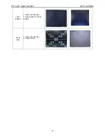
Page 47: ...20 LCD Color Monitor AOC e2040S 47 Light leakage 1 1600 x 900 60 Hz 2 Black pattern or White pattern Fuzzy video 1 1600 x 900 60 Hz 2 Pane picture ...

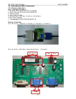
Page 48: ...oft operation system Windows 95 98 2000 XP 3 ISPTool programs 4 VGA cable LPT cable 5 ISP board PN 715GT034 B 715GT048 1 or715GT035 A 6 ISP Firmware Software 7 For example NOVATEK ICNT68668FGQFP 128 Step 2 Connection NO1 TPV Part No 715GT048 1 or 715GT035 A 715GT048 1 or 715GT035 A NO2 TPV Part No 715GT034 B NEW LCD EDID TOOL 715GT034 B To PC LPT Port Connect 12V power To Monitor ...

Page 49: ...040S 49 ISP TOOL front side ISP TOOL reverse side Step 3 Programming 1 Double click the icon to install Port95nt print driver 2 Install tool programme 2 1 decompress Note NT68168F Scale IC must use V4 566 version 2 2 Double click ...

Page 50: ...n and run it 4 Please read the below message For the tool Option FE2P Mode Enable default and for the model please get rid of If it is DATA IN FLASH models need save HSCP KEY of DVI or HDMI models and select Option FE2P Mode Enable Plugins EEPROM Data in 24c16 option FE2P Mode choose disable don t need ...

Page 51: ... e2040S 51 5 Click tool Option choose Setup ISP tool and then choose LPT Port the next choose NVT Type default click Auto Detect to choose the appropriate speed Click Confirm change 6 Click Load File to use the proper software ...

Page 52: ...20 LCD Color Monitor AOC e2040S 52 Click Auto to upgrade F W Appear the dialog box as follow open ...

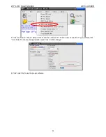
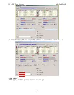
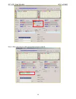
Page 53: ...20 LCD Color Monitor AOC e2040S 53 Click Send MX2026 CMD Click AUTO when appear pass as follow picture that burning is successful AUTO ...

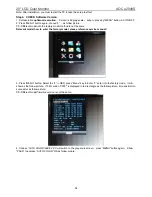
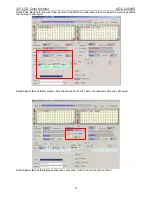
Page 54: ...hod is not the same Relevant model how to enter the factory model please reference service manual 3 Press MENU button Select the F in OSD press Menu key to Enter F enter into the factory mode it will show as the follow picture If FW version V005 is displayed in red rectangle as the follow picture it means Burn In successful as follow picture PS Different model firmware version is not the same 4 Ch...

Page 55: ...ory setting Otherwise monitor will not be able to save setting If not save the setting when AC ON OFF it will can t find the boot LOG from the screen As the below pictures 6 Note If VGA can t be adjusted to the best resolution please rewrite EDID To rewrite EDID please refer to Service Manual The Part No of the EDID tool is 715GT034 B ...

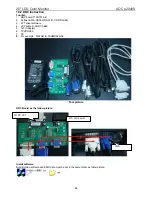
Page 56: ...AT WD DAT CONFIG INI 3 LPT driver software 4 LPT cable D SUB CABLE 5 12V Adapter 6 TPVDDC6 0 7 PC 8 For example MSTAR IC TSUMO58GDJ Tool picture DDC Board as the follow picture Install software Note Burning softsare and EDID data must be put in the same folder as follow picture TO PC LPT DC 12V power VGA ...

Page 57: ...n restart the computer Double click select Analog show as follow picture Note The way of digital DDC Write is the other same as analog But the Flush need Choose DVI If you write DDC VGA DVI is together Flush Choose Analog and DVI The way of HDMI DDC Write is the same as analog But the Flush need Choose HDMI ...

Page 58: ... DDC VGA HDMI is together Flush Choose Analog and HDMI 2 Choose methods Loadfile ldddc The first letter of the brand size Customer mode Such as choose Analog and then click Loadfile ldddc N NEXGEN 19NXG CHIMEI 96VS 3 Click ok show as follow picture ...

Page 59: ...tor AOC e2040S 59 4 Input same SN twice and date Click Pragram to burn When appear pass as follow picture that burning is successful 5 Click program Note 1 Appear fault as follow please input SN twice and burning again ...

Page 60: ...20 LCD Color Monitor AOC e2040S 60 Note 2 When appear pass as follow picture that burning is successful ...

Page 61: ...If read SN and model name are same as before inputing as before that burning is successful Note4 Appear fault as follow please check the connection of LPT cable Tool adapter cable and LCD power Note5 Appear fault as follow please check the connection of VGA and the connection of DVI ...

Page 62: ... not the best achieve 2 For DVI No picture no sound If program failed in VGA mode you can t use the optimal resolution When Read is OK program is NG pls do take following action 1 For VGA cut off the 9th pin connect the monitor 2 For DVI cut off the 14th pin the shortest pin power supply 3 Connect the EEPROM WP pin to ground ...

Page 63: ...with press MODE button 2 Switch the MEM channel to Channel 4 with up or down arrow on chroma 7120 3 The LCD indicator on chroma 7120 will show x 313 30 y 329 30 4 Adjust the RED on factory window until chroma 7120 indicator reached the value R 100 5 Adjust the GREEN on factory window until chroma 7120 indicator reached the value G 100 6 Adjust the BLUE on factory window until chroma 7120 indicator...

Page 64: ...hroma 7120 RGB value meet the tolerance 100 5 D Adjust sRGB color temperature 1 Switch the chroma 7120 to RGB Mode with press MODE button 2 Switch the MEM channel to Channel 4 with up or down arrow on chroma 7120 3 The LCD indicator on chroma 7120 will show x 313 30 y 329 30 4 Adjust the RED on factory window until chroma 7120 indicator reached the value R 100 5 Adjust the GREEN on factory window ...

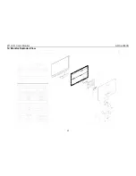
Page 65: ...20 LCD Color Monitor AOC e2040S 65 12 Monitor Exploded View ...

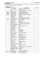
Page 66: ...TER BOARD H01G6009 1 Screw H15G0035101402 MAIN FRAME H33G0022 1 1L LENS_AOC_L201WA 2040LED H33G0023AED 1B KEY PAD_AOC_L201WA 2040LED H34G0045DAVE1M0130 BEZEL H40G 58361513A win7 EPEAT EPA LABEL H41G780961523A QSG H44GA009101 PULP H44GA009201 PULP H44GA009615 3A e2040S carton H45G 77 6 PE PACKING H45G 87 1 23 EPE COVER H45G 87 1810H A EPE COVER FOR BASE H52G6025 16 58 mylar H70G201061523A e2040S CD...

Page 67: ...ty card 808GE2040SVIE E2040S Vietnam ASS Y E08902 089G 715HAAE01 SIGNAL CABLE E08901 089G404A15N HL POWER CORD H26G 800504 2A barcode H40G 22E61552A ID LABEL H40G 58361551A e2040S CARTON LABEL 040G 154501 1 HI POT GND LABEL 040G 45762412B CBPC LABEL 045G 88525 E PE BAG IC902 056G 139 3A PC123Y22FZOF SHARP NR901 061G 58005 X RST NTCR 5R 20 3A 2 6W R904 061G152M47858G SY RST MOFR 0 47 OHM 5 2WS C903...

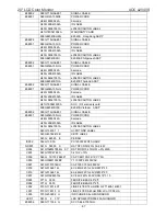
Page 68: ...68AFG QFP 128 U704 056G 563113 IC G1117 18T63Uf 1A 1 8V SOT 223 U705 056G 563215 IC DC DC MP1584EN SOIC8E U702 056G 563512 IC G1117 33T43UF 1A 3 3V TO 252 U103 056G 662502 IC ESD AZC199 04S R7G SOT23 6L U104 056G 662502 IC ESD AZC199 04S R7G SOT23 6L U101 056G1133918 NO SUGGEST AT24C02BN SH T 2kb SO 8 U402 056G2233 11 IC Pm25LD020C SCE SIOC 8 150mil 2M Q402 057G 417517 Tra LMBT3906LT1G 200mA 40V S...

Page 69: ... 16W YAGEO R434 061G0402105 JY RST CHIPR 1000KOHM 1 16W YAGEO R714 061G04021301FY RST CHIPR 1K3 1 1 16W YAGEO R107 061G0402222 JY RST CHIPR 2 2KOHM 5 1 16W YAGEO R106 061G0402222 JY RST CHIPR 2 2KOHM 5 1 16W YAGEO R123 061G0402223 JY RST CHIPR 22KOHM 5 1 16W YAGEO R304 061G0402223 JY RST CHIPR 22KOHM 5 1 16W YAGEO R704 061G0402223 JY RST CHIPR 22KOHM 5 1 16W YAGEO R416 061G0402224 JY RST CHIPR 220...

Page 70: ...210412K Y CAP CHIP 0402 100N 16V X7R 10 C438 065G040210412K Y CAP CHIP 0402 100N 16V X7R 10 C702 065G040210412K Y CAP CHIP 0402 100N 16V X7R 10 C705 065G040210412K Y CAP CHIP 0402 100N 16V X7R 10 C706 065G040210412K Y CAP CHIP 0402 100N 16V X7R 10 C708 065G040210412K Y CAP CHIP 0402 100N 16V X7R 10 C709 065G040210412K Y CAP CHIP 0402 100N 16V X7R 10 C713 065G040210412K Y CAP CHIP 0402 100N 16V X7R...

Page 71: ... 065G060310512K A NO SUGGEST CAP CHIP 0603 1UF K 16V X7R C424 065G060310512K A NO SUGGEST CAP CHIP 0603 1UF K 16V X7R C404 065G0805475A2K Y CAP CHIP 0805 4 7UF K 10V X7R C406 065G0805475A2K Y CAP CHIP 0805 4 7UF K 10V X7R C413 065G0805475A2K Y CAP CHIP 0805 4 7UF K 10V X7R C416 065G0805475A2K Y CAP CHIP 0805 4 7UF K 10V X7R C421 065G0805475A2K Y CAP CHIP 0805 4 7UF K 10V X7R C423 065G0805475A2K Y ...

Page 72: ...6 061G08051152FT RST CHIPR 11 5KOHM 1 1 8W TZAI YUAN R941 061G0805159 JT RST CHIP 1R5 1 8W 5 R922 061G0805471 JT RST CHIPR 470OHM 5 1 8W TZAI YUAN JR901 061G12060007JT RST CHIPR MAX 0R05 1 4W 1206 R908 061G1206101 JT RST CHIPR 100 OHM 5 1 4W TZAI YUAN R914 061G1206101 JT RST CHIPR 100 OHM 5 1 4W TZAI YUAN R934 061G1206103 JT RST CHIPR 10KOHM 5 1 4W TZAI YUAN R906 061G1206103 JT RST CHIPR 10KOHM 5 ...

Page 73: ...0805304 JT RST CHIP 300K 1 8W 5 TZAI YUAN R826 061G0805339 JT RST CHIP 3 3R 1 8W 5 TZAI YUAN R818 061G1206000 JF RST CHIPR MAX0R05 1 4W FENGHUA R811 061G1206308 JF RST CHIPR 0 3 OHM 5 1 4W FENGHUA R812 061G1206308 JF RST CHIPR 0 3 OHM 5 1 4W FENGHUA C806 065G060310131J F CAP CHIP 0603 100PF J 50V NPO C802 065G060368332K F CAP CHIP 0603 68NF K 50V X7R C809 065G080510432K A CAP CHIP 0805 0 1UF K 50V...

Page 74: ...R CONNECTOR 6P 1 25 R002 061G0603000 FF RST CHIPR MAX0R01 1 10W FENGHUA R004 061G06031001FF RST CHIPR 1 KOHM 1 1 10W FENGHUA R003 061G06032001FF RST CHIP 2KOHM 1 1 10W FENGHUA R001 061G06032001FF RST CHIP 2KOHM 1 1 10W FENGHUA C001 065G060310432K A CAP CHIP 0603 100nF K 50V X7R C002 065G060310432K A CAP CHIP 0603 100nF K 50V X7R LED001 081G 14 12 GP CHIP LED GPTD1210YBC5 D E715 715G4014K01000004C ...

Reviews: