19
″
/22
″
/24
″
LED TV AOC LE19D1331/30-LE22D1331/30-LE24D1331/30
Copyright © 2013 by TPV Corporation. All rights reserved. Specifications are subject to change without notice.
No part of this publication may be reproduced in any form or means, without the prior written permission of TPV Corporation.
Otherwise we will reserve the right to investigate the legal responsibility.
1
Service
Service
Service
TABLE OF CONTENTS
Description
Page Description Page
SAFETY NOTICE
ANY PERSON ATTEMPTING TO SERVICE THIS CHASSIS MUST FAMILIARIZE HIMSELF WITH THE CHASSIS
AND BE AWARE OF THE NECESSARY SAFETY PRECAUTIONS TO BE USED WHEN SERVICING
ELECTRONIC EQUIPMENT CONTAINING HIGH VOLTAGES.
CAUTION: USE A SEPARATE ISOLATION TRANSFOMER FOR THIS UNIT WHEN SERVICING
6.1 Main Board……...…………..….…….……….......25
6.2 Power Board……...…………..….…….……….......27
6.3 IR Board…...…………………………………….......29
6.4 Key Board…………………………………...……….30
7. Adjustment..............................................................31
8. Block Diagram…..…………....………………...32
9. Schematic Diagram…..…………....………………...33
9.1 Main Board…………..….….……...………….......33
9.2 Power Board…………..….….……...………….......43
9.3 IR Board…...…………….……….…………….........45
9.4 Key Board………………………………....….......46
10. Exploded View………………………………….…...47
11. BOM List……………….……………….………….49
Table of Contents.......……....................................…........1
Important Safety Notice.......................................……......2
Revision List…………………………………………………3
1. General Specification..............................……...…........4
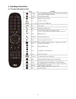
2. Operating Instructions………………...…….……….......5
2.1 The Use of Remote Control…….…..……….…….......5
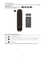
2.2 To Use the Menus….....………………….…..…….......6
2.3 How to Connect……..……………….…….……….....11
2.4 Front Panel Control Knobs…….………….……….....13
3. Input/ Output Specification………....................…....14
4. Mechanical Instructions…………………….................16
5. Repair Flow Chart ……………………….…….…….....19
6. PCB Layout ………………..………………....….......25
Summary of Contents for LE19D1331/30
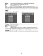
Page 5: ...5 2 Operating Instructions 2 1 The Use of Remote Control ...
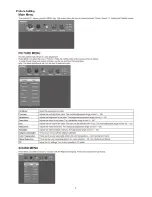
Page 7: ...7 Picture Setting ...
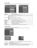
Page 8: ...8 ...
Page 9: ...9 ...
Page 10: ...10 ...
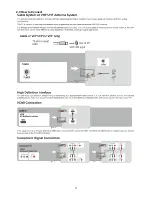
Page 11: ...11 2 3 How to Connect ...
Page 12: ...12 ...
Page 13: ...13 2 4 Front Panel Control Knobs ...
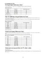
Page 15: ...15 Compatible Mode Table ...
Page 18: ...18 5 Sperate PANEL and BEZEL 6 BEZEL ...
Page 25: ...25 6 PCB Layout 6 1 Main Board 715G5749M01000004K ...
Page 26: ...26 ...
Page 27: ...27 6 2 Power Board 715G5309P01001002S ...
Page 28: ...28 ...
Page 29: ...29 6 3 IR Board 715G5889R01000004S ...
Page 30: ...30 6 4 Key Board 715G5795K01000004S ...
Page 47: ...47 10 Exploded View ...


