33
9. Schematic Diagram
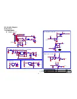
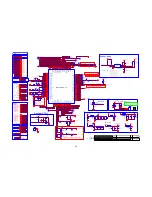
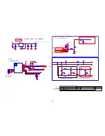
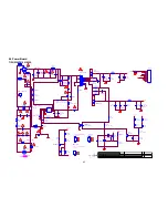
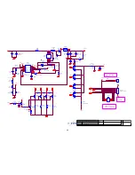
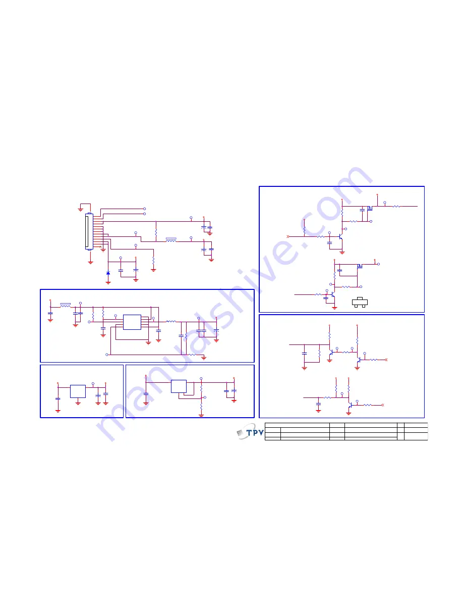
9.1 Main Board
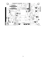
715G5749M01000004K
+
C722
100UF 16V
R2
+1.8V_DDR
DDR Power
Vout = 1.25x(R1+R2)/R2
1.845V
R1
SMT
AUD_PVDD
R711
100K
C719
22UF
Q708
AO3401A
R722
10K
Q709
MMBT3904
R729
4.7K
+3.3V_Standby
+3.3V
+
C736
100uF 35V
C720
22UF
C715
22PF 50V
C709
22UF
OEM MODEL
Size
Rev
Date
Sheet
of
TPV MODEL
PCB NAME
称 爹
T P V ( Top Victory Electronics Co . , Ltd. )
Key Component
絬
隔
瓜
絪
腹
A
Custom
4
13
Thursday , December 06, 2012
<
称爹
>
04. Power
C724
10UF 10V
From Power Board:
24V : G5508(29"),G5193(39")
16V : G5309(19",22",24")
PWR_ON
C716
1uF 10V
R720
10K
+3.3V_Standby
VI
3
VO
2
GN
D
1
4
4
U703
AZ1117H-ADJ-E1
TP1
TP2
TP3
TP4
TP5
TP6
TP7
TP8
TP11
TP12
TP13
TP9
C723
NC 22UF
PS_ON
TP10
TP14
TP15
TP16
TP18
TP20
TP17
TP19
R715
11.5K 1%
TP21
TP23
R717 20K
TP22
VCC
1
POK
2
GND
3
FB
4
EN
5
PGND
6
LX
7
VIN
8
E-Pad
9
U701
APW7323
C710
10UF 10V
+
C717
NC/330UF 6.3V
1
2
FB701
300R 4A
L701
2.2uH
+5V_Standby
+1.2V_VDDC
Vout = 0.8*(1+R1/R2)
R1
073G253S 68 H
MST6831 Core Power = 1.26V/650mA
BL_EN
High active
R714
1K
R706
NC/10K
NC/4.7UF 10V
C706
+
C713
100UF 16V
1
2
ZD701
NC/BZT52-C5V6
R702
1K
R710 4.7K
R708
NC/10K
Q701
AO3401A
C739
100N 50V
R704 1K
Q702
MMBT3904
R709 1K
VI
3
VO
2
GN
D
1
U702
AZ1117D
+
C708
100UF 16V
Q703
MMBT3904
R707
1K
C702
NC/10N 50V
Q706
MMBT3904
R703
10K
R723
4.7K
R705
100R
+5V_Standby
+5V_Standby
+5V_Standby
+5V_Normal
+5V_Normal
+3.3V_Standby
+5V_Normal
+3.3V_Standby
PWR_ON
5
VBL_CTRL
5
BRI_ADJ-PWM0 5
12V
SMT
24V/16V
5V
13P R/A 2.0mm
311GW200A13ADJ
Backlight Control
BL_EN
C737
100N 50V
Q707
MMBT3904
C701
100N 16V
C714
100N 16V
R780 47K
TP24
TP25
TP26
TP27
TP28
C707
100N 16V
PWR_ON
TP349
R727 4.7K
R781
10OHM1/16W
+3.3V
BL_PWM
Low active
High active
1
2
3
4
5
6
7
8
9
10
11
12
13
14
15
CN701
CONN
C712
1uF 10V
System power control
C718
1uF 10V
1
2
FB603
300R 4A
P12V
R737
NC 0R051/8W
+5V_Normal
R728
10K
Standby Power
R719
220R 1%
C773
100N 16V
C772
470nF 16V
C774
470nF 16V
+
C738
100uF 35V
B
E
C
C775
NC/100N 16V
BL_PWM
PS_ON
R721
100R 1%
R701
2.2R 1%
Summary of Contents for LE19D1331/30
Page 5: ...5 2 Operating Instructions 2 1 The Use of Remote Control ...
Page 7: ...7 Picture Setting ...
Page 8: ...8 ...
Page 9: ...9 ...
Page 10: ...10 ...
Page 11: ...11 2 3 How to Connect ...
Page 12: ...12 ...
Page 13: ...13 2 4 Front Panel Control Knobs ...
Page 15: ...15 Compatible Mode Table ...
Page 18: ...18 5 Sperate PANEL and BEZEL 6 BEZEL ...
Page 25: ...25 6 PCB Layout 6 1 Main Board 715G5749M01000004K ...
Page 26: ...26 ...
Page 27: ...27 6 2 Power Board 715G5309P01001002S ...
Page 28: ...28 ...
Page 29: ...29 6 3 IR Board 715G5889R01000004S ...
Page 30: ...30 6 4 Key Board 715G5795K01000004S ...
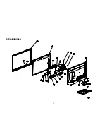
Page 47: ...47 10 Exploded View ...


