21
T2442e
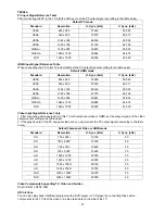
PC Input Signal Reference Table
After connecting the PC to the TV with the VGA port, set the PC output signal according to the table below.
Default PC mode
Standard
Resolution
H. Sync. (kHz)
V. Sync. (kHz)
VESA
640 x 480
31.469
59.940
VESA
800 x 600
37.879
60.317
VESA
1024 x 768
48.363
60.004
VESA
1360 x 768
47.720
59.799
WXGA+
1400 x 900
59.887
55.935
WSXGA
1680 x 1050
59.884
64.674
FHD
1920 x 1080
60.000
67.500
HDMI Input Signal Reference Table
When connecting the PC to this TV with HDMI, set the PC output signal according to the table below.
Default HDMI mode
Standard
Resolution
H. Sync. (kHz)
V. Sync. (kHz)
VESA
640 x 480
31.469
59.940
VESA
800 x 600
37.879
60.317
VESA
1024 x 768
48.363
60.004
VESA
1360 x 768
47.720
59.799
WXGA+
1400 x 900
59.887
55.935
WSXGA
1680 x 1050
59.884
64.674
FHD
1920 x 1080
60.000
67.500
Video Input Signal Reference Table
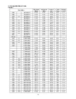
1. After connecting video equipment to this TV with component video or HDMI, set the output signals of the video
equipment according to the table below.
2. If the graphic card of the PC supports video out, you can also set the PC output signals according to the table
below.
Default Component Video or HDMI mode
Standard
Resolution
H. Sync. (kHz)
V. Sync. (kHz)
SD
720 x 480i
15.734
60
SD
720 x 480P
31.500
60
SD
720 x 576i
15.625
50
SD
720 x 576P
31.250
50
HD
1280 x 720P
37.500
50
HD
1280 x 720P
45.000
60
HD
1920 x 1080i
28.125
50
HD
1920 x 1080i
33.750
60
FHD
1920 x 1080P
56.300
50
FHD
1920 x 1080P
67.500
60
Video Components Supporting TV, Video and S-video
PAL D/K B/G I; NTSC M/N.
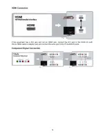
HD Interface
You can also play back traditional programs with a DVD player or VCR player by connecting these video
components to the TV from the video or S-video terminals on the side of the TV.
Summary of Contents for T2242we
Page 6: ...6 2 2 To Use the Menus Using TV Features ...
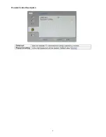
Page 7: ...7 Parental Control Description ...
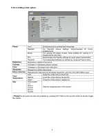
Page 8: ...8 Picture Settings Descriptions ...
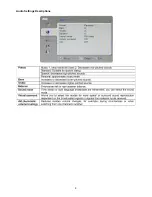
Page 9: ...9 Audio Settings Descriptions ...
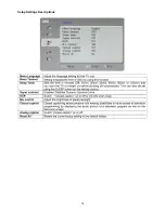
Page 10: ...10 Tune Settings Descriptions ...
Page 11: ...11 PC Image Settings Descriptions ...
Page 12: ...12 Setup Settings Descriptions ...
Page 13: ...13 2 3 How to Connect Connecting TV ...
Page 14: ...14 ...
Page 15: ...15 ...
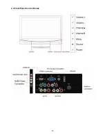
Page 16: ...16 2 4 Front Panel Control Knobs ...
Page 17: ...17 ...
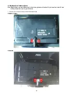
Page 23: ...23 2 Unscrew the 10 screws to remove REAR COVER T942We T2442e T2242We ...
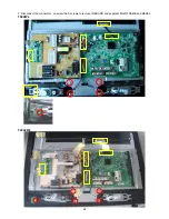
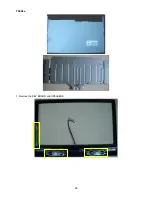
Page 26: ...26 T2242We T2442e 6 The PANEL and MAIN FRAME T942We ...
Page 27: ...27 T2242We ...
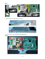
Page 28: ...28 T2442e 7 Remove the KEY BOARD and SPEAKERS ...
Page 36: ...36 6 PCB Layout 6 1 Main Board T942We T2242we 715G3983M0E000004F ...
Page 37: ...37 ...
Page 38: ...38 T2442e 715G3983M01001004L ...
Page 39: ...39 ...
Page 40: ...40 6 2 Power Board 715G3973P01W21003S ...
Page 41: ...41 ...
Page 42: ...42 ...
Page 43: ...43 T942we 715G3918P03000004F ...
Page 44: ...44 ...
Page 45: ...45 Converter Board 715G3977P04000004L ...
Page 46: ...46 6 3 Key Board 715G4066K01000004S 6 4 IR Board 715G4079R01000004S ...
Page 76: ...76 10 Exploded View ...

