02
Nomenclature and Functions
- 0 -
For Veterinary use only
Nomenclature
Description
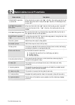
1. RIGHT/LEFT angulation
control knob
When this knob is
turned in the “R
▲”
direction, the bending section moves
RIGHT.
When the knob is turned in the “
▲
L” direction, the bending section
moves LEFT.
2. UP/DOWN angulation
control knob
When turn this knob in the “
▲
U” direction, the bending section moves UP;
when turn this knob in the
“
D
▲”
direction, the bending section moves
DOWN.
3. UP/DOWN angulation lock Moving this lock in the “F ” direction frees angulation. Moving the lock in
the opposite direction locks angulation.
4. RIGHT/LEFT angulation
lock
Turning this lock in the
“F ” direction frees angulation. Turning the lock in the
opposite direction locks angulation.
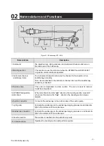
5. Suction cylinder
Attach the suction valve to this cylinder.
6. Air/water cylinder
Attach the air/water valve to this cylinder.
7. Biopsy Valve
This valve is attached to the instrument channel inlet, and the endotherapy
accessory is inserted, or a syringe is attached
8. Instrument channel
The instrument channel functions as:
⚫
channel for the insertion of an endotherapy accessory
⚫
suction channel
⚫
fluid feed channel
9. Insertion tube limit mark
This mark shows the maximum point to which the endoscope may be
inserted into the patient’s body.
10. Distal end
The objective lens and air/water nozzle are on this distal end of the
endoscope.
11. Bending section
This section moves the distal end when the UP/DOWN and RIGTH/LEFT
angulation control knobs are operated.
12. Insertion section
This section is inserted into the patient body cavity.
13. Control section
Operates the bending section, feeds air and water, and performs suction.
14. Optional buttons
The functions of the buttons can be selected on the endoscope imaging
processor.

