04
Operation
For veterinary use only
-
22 -
4.4.1
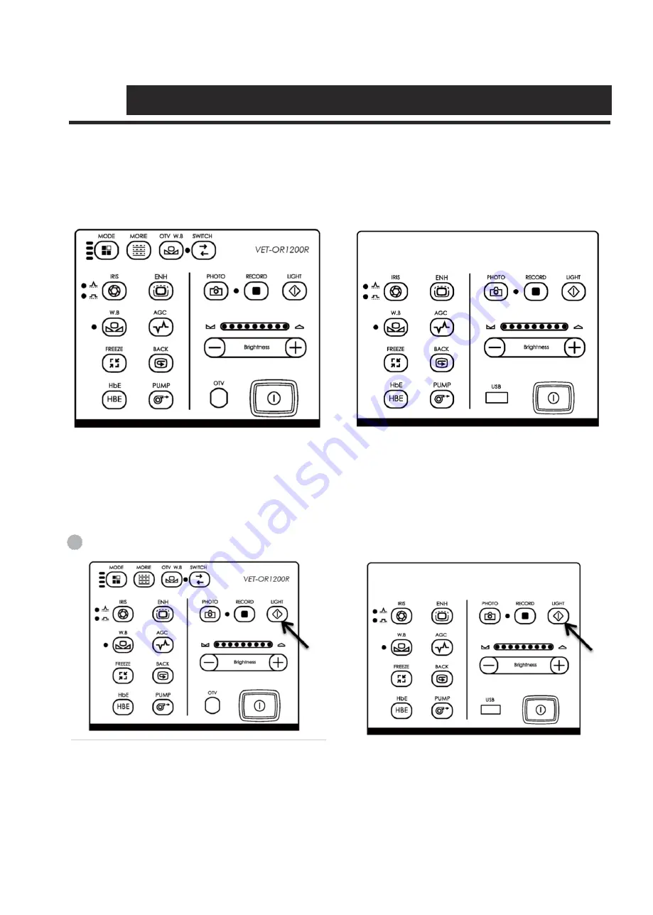
Schematic diagram of panel
The schematic diagram of the panel button layout of the VET series imaging processor is shown in the Figure
4.4.1. Press the panel buttons to perform panel operations.
a. VET-OR1200R
b.VET-OR1200HD, VET-OR1200HD-Li
( Figure 4.4.1 Schematic diagram of the panel buttons)
4.4.2
Examination lamp ignition
This operation turns the examination lamp ON.
Press the Light button on the front panel. See the Figure 4.4.2.
a. VET-OR1200R
b.VET-OR1200HD, VET-OR1200HD-Li
(Figure 4.4.2)
1
Summary of Contents for VET-OR1200HD
Page 1: ......


