background image

F

Button

RESET

* Restart the weather station

Alarm 2 on/off switching button

Alarm 1 on/off switching button

I

Button

HISTORY

* Display air pressure value of previous hours ( 0 ~ -12 hours)

* Activate air pressure setting mode

* Save changes to settings

J

Button

CITY

* Activate city setting mode

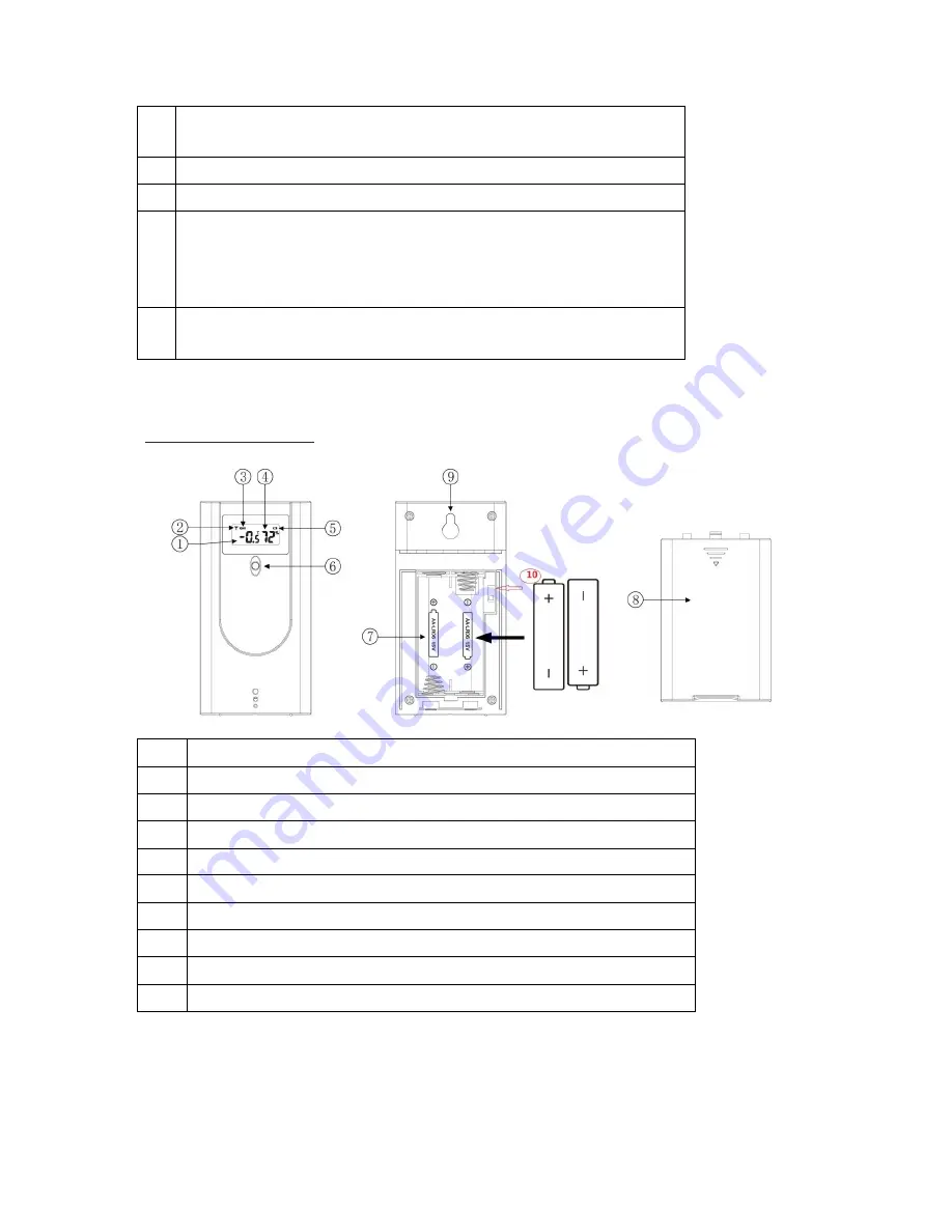
Wireless sensor

1

Temperature display

2

Radio frequency display

3

Current transmission channel

4

Humidity display

5

Low battery indicator

6

Red pilot light

7

Battery compartment

8

Battery compartment cover

9

Loop for hanging

10

Sliding switch 1 2 3: Set sensor number (transmission channel)

If you wish to use only the wireless sensor included in the delivery, as a general rule, the transmission

channel does not need to be changed.

This is only necessary if you wish to use additional wireless sensors; see “Using additional wireless

sensors”.

Summary of Contents for TX2056A

Page 1: ...2 batteries LR6 type AA 1 5 V wireless sensor Operating instructions Product functions Weather station 12 or 24 hour display Date time and day of week display 2 alarms can be set with snooze function...

Page 2: ...Wall mounting bracket Wireless sensor Temperature display in C F Humidity display Range of up to 100 meters in open area Low battery indicator Wall mounting bracket Overview the Weather Station...

Page 3: ...switching symbol 11 Sun rise 35 Current transmission channel to the base unit 12 BBQ symbol 36 Radio frequency reception symbol 13 Sun set 37 Outdoor temperature alert symbol 14 Air pressure trend 38...

Page 4: ...Save changes to settings C Button Set values increase Display stored MAX and MIN values D Button Set values decrease Switching outdoor temperature alert and frost warning on off Activate outdoor temp...

Page 5: ...ture display 2 Radio frequency display 3 Current transmission channel 4 Humidity display 5 Low battery indicator 6 Red pilot light 7 Battery compartment 8 Battery compartment cover 9 Loop for hanging...

Page 6: ...ate the weather station with up to three wireless sensors The wireless sensors can be located in different rooms or outdoors Every sensor must be assigned its own sensor number number of the transmiss...

Page 7: ...h to RC receiving mode the receiving symbol will flash and the number of radio waves on display indicates the quality of reception The more radio waves on display the better the reception As soon as t...

Page 8: ...mat the afternoon hours are shown with PM on the display 3 Press MODE to store the setting 4 Continue as described Set a value with and Store a setting with MODE 5 Set the following settings one after...

Page 9: ...cal cables gas or water pipes in the wall at the installation site Otherwise there is a risk of electric shock You can put the base unit on the desk or hang it up Wireless sensor Place or hang the wir...

Page 10: ...n the base unit apart from SNOOZE LIGHT to stop the alarm The alarm will go off again after 24 hours Automatic stop function If you do not press any buttons the alarm will automatically switch off aft...

Page 11: ...temperature and humidity values by repeatedly pressing the button press once the maximum values are shown press again the minimum values are shown press again returns to normal display Press and hold...

Page 12: ...the channel which has been set Only Alert symbol will flash with beep sounds if the current channel is not the channel which has been set Frost warning If the wireless sensor measures a temperature be...

Page 13: ...ain the symbols display continuously again An arrow shows the weather tendency rising air pressure weather will improve constant air pressure weather will stay the same falling air pressure weather wi...

Page 14: ...battery symbol is shown on the display you have to replace the batteries in the base unit battery symbol in indoor area or the wireless sensor battery symbol in outdoor area with new batteries Note Th...

Page 15: ...es are above or below the measuring range see Technical Data The base unit is not receiving any signal from the wireless sensor Make sure that there are no electrical sources of disturbance near the w...

Page 16: ...sly approved by the party responsible for compliance could void the user s authority to operate the equipment NOTE This equipment has been tested and found to comply with the limits for a Class B digi...

Page 17: ...Connect the equipment into an outlet on a circuit different from that to which the receiver is connected Consult the dealer or an experienced radio TV technician for help...

Reviews: