background image

AO S H igh   Sp e ed   Ca m era s  


Ve rs io n   1 .1 . 3  


C o p y r i g h t  

©

A O S   T e c h n o l o g i e s   A G  


P a g e   2 0   o f   3 2  


7.2.2


HDMI Interface (option) 

Th e  AO S H igh   Sp e ed   ca m eras   ar e  op tio n al ly   av aila b l e  wi th  a  HD MI v id eo  ou tp u t .  Th is   HD MI  
mu s t  b e  ord er ed  to ge th er  w ith   th e  ca m e ra.   


Li mit ati on s  
De f in it ion  o f H DM I is   fo u n d  h e r e: 

h ttp s :/ / en . wi kip ed ia .or g /w ik i/H D MI


7.2.3


I/O Channels 

E ach   AO S H igh  Sp e ed   Ca m era  f ea tu r es  I /O - Ch an n els   to  ei th er a c ce p t  ex ter n al s ig n als   (i . e. 
p os it ion in g s w itch )  or t o p rov id e a d ig ita l 

ou tp u t s ig n al  ( i. e. “ tr ig g er o u t”) .


Th e  AO S H igh   Sp e ed   Ca m era   o ff e r p os s i b il it ies   to f it  a s i gn a l as   in - or  
ou tp u t  ac cor d in g c u s to m er n e ed s .  C on ta ct u s   u n d er  

in f o@ aos t e ch n o lo g i es . c om

   f or d is cu s s in g  you r   n e ed s .  


7.2.4


Wi-Fi Connection 

Th e  Wi -F i  con n e cti on  c a n  b e  u s ed  to  con t ro l th e  ca m era .   Th e  C -S er i es  c a m era  s u p p or t 2 .4 G Hz 
an d  5 GH z.  
To  g et t h e  b es t  th rou gh p u t c on s id er  th e  fol lo wi n g p o in ts :  

-


Con n e ct th e  ac c es s  p o in t w ith   a g ig ab it   e th ern e t cab l e to  th e P C  (n ot  W ir el es s ) .  

-


5G Hz h as  in   m os t  cas es   b ett e r p er fo rm an c e  th a n  2. 4 GHz .  

-


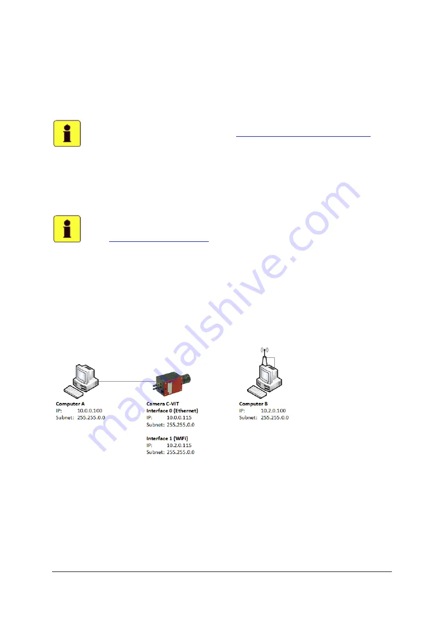
Cab le  an d   Wi - Fi  con n e ct ion s   mu s t b e  in  d i ff e ren t s u b n ets .  

 
Th e a tta ch ed  s k et ch  s h o ws  a  typ i ca l I P s e tu p :  


Summary of Contents for C-Series

Page 1: ...S High Speed Cameras Camera Manual C Series AOS Technologies AG Taefernstrasse 20 CH 5405 Baden Daettwil Switzerland Tel 41 56 483 3488 fax 41 56 483 3489 info aostechnologies com www aostechnologies com ...

Page 2: ... 4 1 1 The Camera Rear Panel 10 4 1 2 The Camera Front Panel 11 5 LED 12 5 1 1 Status LED s 12 5 1 2 Data Interface LED part of Ethernet Connector 15 6 OPERATION MODES 16 6 1 1 Sleep mode 16 6 1 2 Ready mode 16 6 1 3 Pre triggering mode 17 6 1 4 Recording mode 17 7 SYSTEM SETUP 18 7 1 1 Scope of supply 18 7 2 System Extensions optional 19 7 2 1 Non Volatile Memory optional 19 7 2 2 HDMI Interface ...

Page 3: ...red filter 26 10 TROUBLESHOOTING 27 11 APPENDICES 28 11 1 Description of external input and output signals 28 11 1 1 Pinout I O Connector 28 11 1 2 Connector reference 29 11 1 3 Universal I O description 29 12 CE DECLARATION 30 13 LIMITED LIABILITY 31 14 OPTIONS AND ACCESSORIES 32 14 1 1 Pigtail cable AOS part 2200117 32 14 1 2 Camera Hubs 32 ...

Page 4: ...retation of measurements and or interpretation of recordings taken with the camera It is the sole responsibility of the user to successfully record and or interpret any information collected by using this camera Copyright The information in this manual is subject to changes without any prior notice and supplied as is AOS Technologies makes no warranty of any kind with regards of the information pr...

Page 5: ...nformation required for a smooth operation of AOS High Speed Camera General description of AOS High Speed Camera AOS High Speed Camera is a high speed camera capable of record and store data in its built in camera memory The rechargeable battery allows operation of up to 15 minutes autonomous time and up to 30 mins stand by time Unpacking Check of completeness Unpack your camera from its transport...

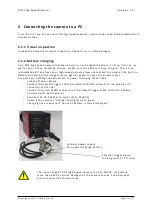
Page 6: ...he built in battery will protect the image memory against power failures and power losses Connect your AOS high speed camera to power following these steps switch off your camera connect the Power Trigger cable included with each camera to the cameras I O connector at the rear connect the 2 pin LEMO connector of the Power Trigger cable to the DC Adapter included with each camera Connect the DC Ada...

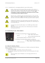
Page 7: ...kind of warranty is immediately void if batteries are replaced by non authorized personnel The batteries used in the AOS cameras are of NiMH typ e Nickel metal hydride When disposing the camera make sure to follow proper environmental handling and guidelines 2 1 3 Switching on and off procedure 1 Switching on standard when camera is switched off press Power push button shortly wait until startup s...

Page 8: ...unpowered for min 30 sec before switch on again When switching on the camera within 30 sec after power down some setting may not be deleted due to camera internal power management reasons Note When it is necessary to reset the camera hold the reset button pressed for a minimum of 1 sec Otherwise faulty settings may be loaded 2 1 6 Connecting the camera to a PC Your AOS camera does not need a speci...

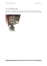
Page 9: ...ght AOS Technologies AG Page 9 of 32 2 1 7 C VIT Ethernet Port C VIT offers a lockable Ethernet connection link to PC is desired in e g Hi gh G crash tests Alternatively a standard Ethernet cable with RJ45 connectors are of CAT6 type can be used ...

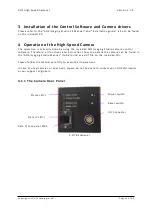
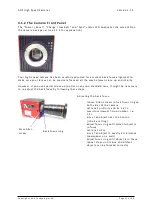
Page 10: ...he included AOS Imaging Studio camera control software Therefore all functions and instructions how to op erate the camera can be found in the AOS Imaging Studio Manual to be found as a pdf file on the included CD Please follow the manual carefully to execute all operations In case of uncertainties or questions please do not hesitate to contact your A OS distributor or our support engineers 4 1 1 ...

Page 11: ... if you use special close up optics or any non standard lens it might be necessary to re adjust the back focus by following these steps Adjusting the back focus loosen Allen screws to free focus ring on both sides of the camera set lens to infinity and its iris to maximum lowest f stop number i e 1 4 aim at an object near the horizon infinite setting adjust focus ring until distant object is in fo...

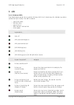
Page 12: ...ched off Camera on normal mode Camera has been switched on normally by the power push button Camera on Factory reset mode Power push button has been pressed for 4 secs Camera starts in the Factory Reset Mode and resets all parameters to Factory Default values before camera switches off Camera on battery and switch on LED is blinking 3 times Battery has low charge the camera must be connected to po...

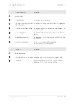
Page 13: ...t detected or defective Connect power and charge for approx 10mins If status remains unchanged contact your distributor or support aostechnologies com System Error LED Remarks Booting error Switch off camera power switch or reset camera reset switch If camera does not start contact your AOS partner Start up sequence Camera will be in normal mode within seconds Start up sequence completed normal mo...

Page 14: ...aiting to receive the trigger signal to start recording Camera triggered Camera continues recording until image memory is full Image data download Image data is being downloaded to PC or internal CF memory Download completed Download of image data completed Next recording can be started Sync LED Remarks No external sync External sync signal received External sync signal controls the image clock Sy...

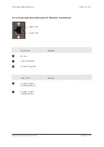
Page 15: ... AOS Technologies AG Page 15 of 32 5 1 2 Data Interface LED part of Ethernet Connector Upper LED Remarks No link Link established Transferring data Lower LED Remarks Transfer speed 10 100 Mbits sec Transfer speed 1000 Mbits sec Upper LED Lower LED ...

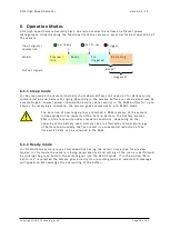
Page 16: ...AM memory of the camera is depending on the capacity of the built in battery The battery assures 30min of data security under standard conditions depending on the capacity of the battery used Battery time is affected by temperature age of battery and humidity that can result in a substantial reduction of the time which data can be retained in the RAM 6 1 2 Ready mode In this mode the camera runs a...

Page 17: ...the back of the camera start flashing When you put the camera into PRE TRIGGERED mode via the PC be sure you have not disconnected the Ethernet link The Ethernet link may be disconnected after the camera is in PRE TRIGGERED mode 6 1 4 Recording mode In this mode the camera finishes the ongoing recording and then awaits access reconnection of the Ethernet link The camera automatically goes into a p...

Page 18: ...mera is delivered with the following high speed camera Power Trigger Adapter cable 0 5m Ethernet data cable power supply 110 230VDC 24VDC Add Ons Add ons are extension modules especially designed for your AOS high speed camera and will extend the functionality of your camera for your specific applications Some add ons have to be purchased with the camera i e the CF ast interface others may be purc...

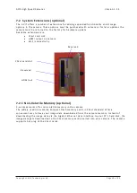
Page 19: ...Fast card slot HDMI output on camera Wi Fi connectivity 7 2 1 Non Volatile Memory optional C series cameras offer non volatile memory in the camera The widely used non volatile Compact Flash memory cards in CFast standard offer a convenient way to have your image data downloaded from the camera memory Instead of downloading the image data via the Gigabit Ethernet data interface to your PC s hard d...

Page 20: ...h or to provide a digital output signal i e trigger out The AOS High Speed Camera offer possibilities to fit a signal as in or output according customer needs Contact us under info aostechnologies com for discussing your needs 7 2 4 Wi Fi Connection The Wi Fi connection can be used to control the camera The C Series camera support 2 4GHz and 5GHz To get the best throughput consider the following p...

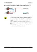
Page 21: ...e control PC 8 1 1 Multi camera systems without frame synchronization If cameras have to or can be operated independently without frame synchronization the cameras can simply be connected using their GigE data interface and CAT6 cables To bridge longer distances commercially available GigE network components like Bridges Hubs and Routers can be used The trigger signal has to be provided to each in...

Page 22: ...t arts at the very same time to avoid time slip Time slip due to failing synchronization Phase lock frame synchronization Cam 1 Clock 999 998Hz Cam 2 Clock 1 000 002Hz Frame 1 Frame 2 Frame 4 Frame 3 Frame 5 Frame 1 Frame 2 Frame 5 Frame 4 Frame 3 Trigger T0 Cam 1 Clock 1 000 000Hz Cam 2 Clock 1 000 000Hz Frame 1 Frame 2 Frame 4 Frame 3 Frame 5 Trigger T0 Frame 1 Frame 2 Frame 4 Frame 3 Frame 5 ...

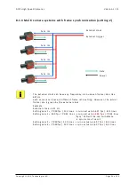
Page 23: ...ync signal on its Sync IN line works as the SLAVE each camera can have a different setup resolution frame rate trigger setting etc the MASTER controls the frame rate of all following SLAVE cameras SLAVE cameras run on the same or a lower frame rate then the MASTER camera Example MASTER 1 000 fps SLAVE 500 fps setting runs actually on 500fps Sync LED will be red to indicate a sync error on the SLAV...

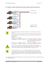
Page 24: ...r the actual frame rate is given by the external clock Example External clock 637 Hz Setting cam 1 1 000fps 512 lines runs actual on 637 fps 512 lines Setting cam 2 500 fps 1 024 lines runs actual on 500 fps 1 024 lines Sync LED will be red to indicate a sync error of cam 2 Setting cam 3 1 000fps 512 lines runs actual on 637 fps 512 lines Setting cam 4 1 000fps 512 lines runs actual on 637 fps 512...

Page 25: ...fps 512 lines runs actual on 500 fps 512 lines Setting cam 4 1 000fps 512 lines runs actual on 500 fps 512 lines Due to the fact the camera providing the Sync signal to all following camera can overrule their setting this system setup daisy chain has to be used with greatest care to avoid sequences at wrong settings If cameras have to or can be operated independently without frame synchronization ...

Page 26: ...ttery in the cameras are considered wear and tear parts an d are not covered by any warranty For environmental protection do not throw away batteries in household waste Dispose batteries safely or return it to AOS technologies or your nearest distributor 9 1 3 Cleaning the AOS High Speed Camera Infrared filter Your AOS High Speed Camera color versions standard does have an optical filter to block ...

Page 27: ...right AOS Technologies AG Page 27 of 32 10 Troubleshooting Despite all quality procedures in design development and production there can be errors in the software The known bugs are listed in the release notes of the specific software release ...

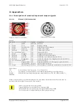
Page 28: ...de Universal I O 2 10 Output Triggered TTL Indicates camera has triggered Universal I O 3 11 In or Output I O 4 TTL Universal I O 4 12 Signal GND TTL Common GND for all I O signals pin 6 9 10 11 13 IRIG B GND IRIG B IRIG B signal ground 14 Input IRIG B signal IRIG B IRIG B signal amplitude modulated standard 122B Definitions TTL 3 3 5V max 36V for pin 6 7 9 10 and 11 V In 10 36VDC nominal 24VDC 12...

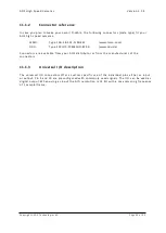
Page 29: ... Type S22LOC P14MFGO 8200 www odu de Connectors are available from your AOS dist ributor or from the manufacturers of the connectors 11 1 3 Universal I O description The universal I O connectors offer a custom specific use of the individual pins either as input or output Pin 9 and 10 are preconfigured with commonly used signals The I O c an be used as digital output When using as input the A D res...

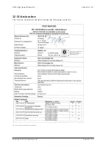
Page 30: ...d Cameras Version 1 1 3 Copyright AOS Technologies AG Page 30 of 32 12 CE declaration The C series have been tested according the following standards F u l l t e s t re p o rt a v a i l a b l e u p o n r e q u e s t ...

Page 31: ...the Purchaser properly packaged to avoid further damage addressed to AOS Taefernstrasse 20 CH 5405 Baden Daettwil Switzerland with transportation and other applicable charges prepaid by the Purchaser The liability of AOS under the foregoing warranty is limited at AOS Technologies option solely to repair or replacement with an equivalent Product which may include a refurbished or previously owned P...

Page 32: ...Sync OUT Output TTL Armed Output TTL Remote On IRIG B Custom functions available on request 14 1 2 Camera Hubs AOS offers a wide selection of camera hubs ranging from 4 cameras up to 12 cameras These hubs may be used on and off board depending on application Please contact your AOS distributor for a complete catalogue with all accessories circuits etc In case we do not have that particular accesso...

Reviews: