AO S H igh Sp e ed Ca m era s
Ve rs io n 1 .1 . 3
C o p y r i g h t
©
A O S T e c h n o l o g i e s A G
P a g e 2 8 o f 3 2
11
Appendices
11.1
Description of external input and output signals
11.1.1
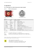
Pinout I/O Connector
1
10
2
11
3
9
4
5
12
6
8
7
14
13
Ca m era : Vi e w o n c on n ec tor
Cab le s id e : F ron t v i e w
Pin ou t
Pin I/O
C -V I T
Si gn al
Fu n c tio n
1
-
GN D
Gr ou n d
Gr ou n d
2
In p u t
V In
VD C
Su p p l y v ol tag e
3
In p u t
Re m ot e On
T TL
S wit ch i n g on th e ca m er a
4
In p u t
Syn c In
T TL
Fra m e s y n c i n p u t
5
Ou tp u t
Syn c Ou t
T TL
Fra m e s y n c ou tp u t
6
In - or Ou tp u t I/O 1
T TL
Un iv e rs al I/ O 1
7
In p u t
Tr ig g er
T TL
Tr ig g er in g th e c a me ra
8
Ou tp u t
Str ob e
T TL
Str ob e ou t f or s t rob e l i g h ts
9
Ou tp u t
Ar m ed
T TL
In d i cat es r e c mod e ( Un i v ers a l I /O 2 )
10
Ou tp u t
Tr ig g er ed
T TL
In d i cat es ca m era h as tr i gg er ed ( Un iv e rs al I/ O 3 )
11
In - or Ou tp u t I/O 4
T TL
Un iv e rs al I/ O 4
12
-
Si gn al GND
T TL
Co m mon GN D fo r a ll I/ O s ign als (p in 6, 9, 10, 11 )
13
-
IRI G - B GND
IRI G - B
IRI G - B s i gn a l g rou n d
14
In p u t
IRI G - B s i gn a l IRI G - B
IRI G - B s i gn a l, a mp lit u d e mod u la ted , s tan d ard 1 22 B
De f in it ion s :
T TL
:
3. 3… 5 V (
m ax. 3 6V fo r p i n 6, 7, 9, 1 0 an d 1 1 )
V In
:
10
…
36 VD C, n o min al 24 V DC , 1 2 -2 5W atts d ep en d i n g on con f igu rat ion
IRI G - B :
IRI G - B 1 2 2 a mp l itu d e m od u lat ed , a mp l itu d e 4 V
p p
, DC : 0V , S NR : 60d B, Z
i n
:
60 0Oh m
Pl eas e in q u ir e w ith y ou r AO S d is tr ib u to rs for av aila b l e I /O - cab les an d o th e r d ev i ces to
con n ec t ext e rn a l s i gn al fro m an d t o th e ca m era .
GN D is con n e ct ed t o h o u s in g GN D
Si gn al GND h as n o co n n ec tion to h ou s in g GN D
IRI G - B GND h as n o c on n ec tion to Si gn a l GN D an d /or G ND
It is in th e
u s e r’s
r es p o n s ib il ity to h av e p rop e r wi rin g.

