6
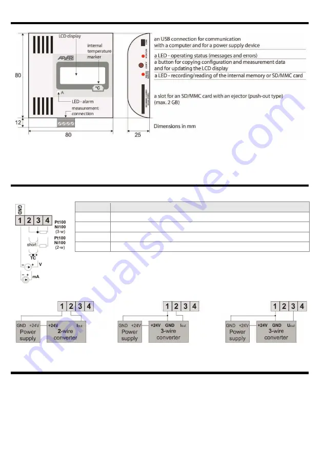
5. HOUSING DIMENSIONS, DESCRIPTION OF CONNECTIONS AND EXTERNAL ELEMENTS
In the case of wall-mounted installation, in order to make mounting holes, the back wall of the housing can be
uninstalled (chapter 14) and used as a template.
6. MEASUREMENT CONNECTOR DESCRIPTION AND THE ELECTRICAL CONNECTIONS
a) numbering of connections and method of connecting sensors and measurement signals
b) connection of a 2- and 3-wire transducer (Iout - output current, Uout - output voltage)
7. CONNECTING TO A COMPUTER AND INSTALLATION OF DRIVERS
After the first connection, the Windows (XP/Vista/7/8/10) system detects the recorder named “
APAR USB DEVICE
”
and demands installation of drivers. In the find new device wizard,
manually
indicate the location of the drivers
on a CD-ROM, the
DRIVERS
catalog).
In the Windows XP system, the installation procedure is the following:
1. Choose the option “
No, not this time
” and press the “
Continue
” button.
2. Choose “
Install from a list or a specific location (advanced)
” and press the “
Continue
” button
3. Select “
Find the best driver in those locations
” and the selection field “
Include this location in the search:
,” press
Terminals
Description
2-3-4
input Pt100, Ni100, resistance (2- and 3-wire)
2-3
thermocouple input TC (J, K, S, B, R, T, E, N) and voltage input 0÷60 mV
1-2
current input 0/4÷20 mA
1-3
voltage input 0÷10 V


