12
b)
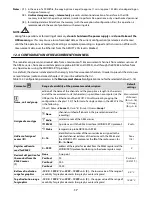
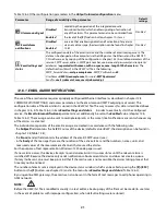
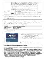
upper status bar
Fig. 11.1.1.
Upper status bar
Object
Description [
and marking in the contents of the instructions
]
1
date (yyyy-mm-dd), day of the week and time (hh:mm:ss) on the real time clock (RTC, chapter 12.10)
2
status of alarm outputs, from the 1st to the 4th (chapter 12.6,
Outputs (alarm) configuration
menu)
gray - the output is switched off (the alarm is inactive);
red (with the numbers of the input channels that activate the alarm) - the output is switched on
3
parameter
Alarm sound signal
is set to the
Enabled
value (chapter 12.6)
all the alarm outputs blocked with the programmable
[F]
button (chapters 10 and 12.9)
4
[R/W]
- signaling of writing to or reading from the internal memory or the USB memory
5
signaling of ongoing recording in the internal memory or the USB memory (
)
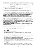
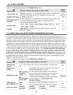
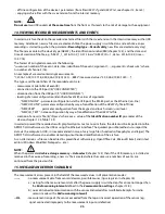
11.2. VIEW OF A MEASUREMENT GROUP (TEXT ONLY)
Fig. 11.2.
Appearance of a measurement group screen in the
TEXT ONLY mode (presentation max. 16 channels is possible)
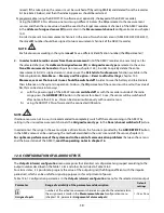
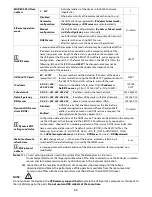
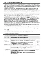
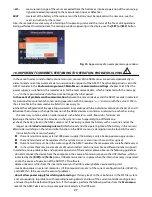
11.3. VIEW OF A MEASUREMENT GROUP (TEXT AND A BAR GRAPH)
Fig. 11.3.
Appearance of a measurement group screen in the
TEXT AND BAR GRAPH mode (presentation max. 8 channels is
possible)
Object
Description
1
status bars (chapter 11.1)
2
measurement panel: number, name (up to 16
characters) and unit (up to 4 characters) of the
measurement channel (name and unit taken
from the
AR407.txt
file, chapters 12.4
and 12.5
),
measured value with signaling of exceeded
measurement range (chapters 12.4, 12.5 and 15)
Object
Description
1
status bars (chapter 11.1)
2
measurement panel: number, name, measured
value, and unit of the measurement channel
(chapter 11.2), graphic presentation of the
measurement (bar graph) works in the range
set by the parameters
Bottom of indication
range for graphics
and
Top of indication
range for graphics
(chapters 12.4 and 12.5)
Summary of Contents for AR407
Page 32: ...32 21 USER S NOTES...


