WWW.APART-AUDIO.COM
6
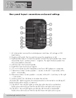
Rear panel layout: connections and sound settings
1
2
7
8
9
10
11
12
3
4
5
6
1. AC inlet socket: connect the included power cord here. AC voltage is 230
VAC/50 Hz.
2. Power on/off switch: flip the switch to power the speaker on or off.
3. Right speaker output: connect the speaker wire for the right speaker here. Mind
the polarity. Red = positive, black = negative. The right channel speaker has
the same speaker connector.
4. Left RCA input for line level signals.
5. Right RCA input for line level signals.
6. 3.2 mm minijack input for headphone outs from MP3 players or computers.
7. Treble tone control. Center position = neutral, to the left = less treble, to the
right = more treble.
8. Bass tone control. Center position = neutral, to the left = less bass, to the right
= more bass.
9. Volume knob. Turn clockwise to increase the volume.
10.Power LED: lights up green when the powercord is connected to a working AC
outlet and the power switch is turned on.
11. Clip LED R: this red LED lights up when the right channel is overloaded.
Reduce the volume (9) so that the clip LED does not light up during use.
12. Clip LED L: this red LED lights up when the left channel is overloaded.
Reduce the volume (9) so that the clip LED does not light up during use.

