8
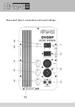
1. Power on/off switch: flip the switch to power the speaker on or off. Always
power off the unit when not in use.
2. AC inlet socket: connect the included power cord here. AC mains voltage is
230VAC ±10%/50-60 Hz. The mains fuse is located inside the cabinet and
must be replaced only with an identical fuse. If the fuse blows up regularly,
have your unit serviced by a qualified service technician.
3. RCA input: 2 identical RCA connectors for unbalanced line level signals. The
line-in and link connector are internally connected in parallel, allowing you to
link the signal through to one or more active speakers.
4. XLR input: male and female XLR connectors for balanced line level signals. The
line-in and link connectors are internally connected in parallel, allowing you to
link the signal through to one or more active speakers.
5. Treble tone control: Center position = neutral. To the left = less treble, to the
right = more treble.
6. Bass tone control: Center position = neutral. To the left = less bass, to the right
= more bass.
7. Volume: turn clockwise to increase the volume. When turned counterclockwise
to the limit, the audio signal present at the inputs is muted.
8. Power LED: lights up green when the power cord is connected to a working AC
outlet and the power switch is turned to the on position.
9. Clip LED: this red LED lights up when the internal power amplifier is
overloaded. Reduce the volume so that the clip LED does not light up during
use. When the sound is distorted, the signal level at the inputs is too high.
Reduce the output from your audio source (pre-amplifier) in such cases.
10. Heat sink: keep the heat sink free from dust, do not cover the heat sink and
ensure sufficient airflow in this area.
Summary of Contents for OVO8-BL
Page 1: ...MANUAL OVO8P ...
Page 6: ...6 vertical use of the speaker increased inclination ...
Page 7: ...7 Rear panel layout connections and sound settings ...
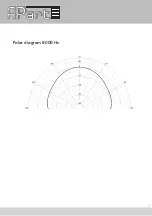
Page 10: ...10 Polar diagram 1000 Hz Polar diagram 4000 Hz ...
Page 11: ...11 Polar diagram 8000 Hz ...
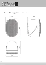
Page 12: ...12 Technical drawing with measurements 244 250 358 244 250 ...
Page 15: ...15 ...


