A54-3144-XR • Rev B
37
APCON, Inc.
ACI-3144-XR Chassis User Manual
Chapter 4. Installation and set up
♦
To prepare for a DC power connection:
1. Secure the conductors in compliance with strain relief regulations defined by your
organization’s governing documentation and practices.
2. Complete power source termination according to standards defined by your
organization’s governing documentation and practices. For example, your rack may
provide an attachment point or there may be grounding from the power source.
3. Fuse at 30 amps per circuit.
♦
To turn ON the chassis using DC power:
After the unit is set up in the location that you want, it is ready to apply power.
1. Attach a power cord to the power supply on the back of the unit.
2. Verify the operating status of each power supply by checking the two LED indicators,
described in the next sections. You can also set alarms in the W
EB
XR interface.
♦
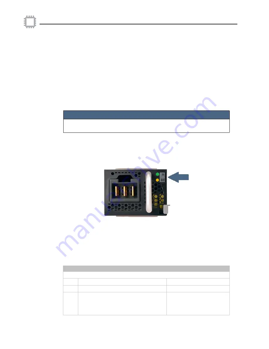
To verify the operating status of each DC power supply:
Check the two LED indicators:
Note the labels beside the LEDs for the DC power supply:
• The upper LED is
green
and indicates whether DC power is on or off. The LED may be
labeled as IN or FAIL.
• The lower LED can display two colors (
green
and
amber
); the color depends on the
presence of DC power or fault situations. The LED may be labeled as OUT or OK.
The following table lists various states for the DC power supply depicted by the LEDs:
NOTE
There is no ON/OFF switch on the chassis; instead, after you insert a power cord
and connect it to the electrical supply, the chassis powers up automatically.
Operating condition
LED signal
Upper
LED
(IN or FAIL)
DC line within range
Solid
green
DC line UV condition
OFF
Redundant operation (if two power supplies
are installed in the chassis). Power supply 1
is operating and power supply 2 has input
power removed.
Solid
amber


