background image

9

3. 

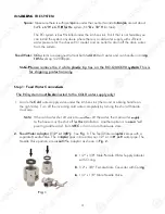
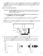
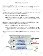
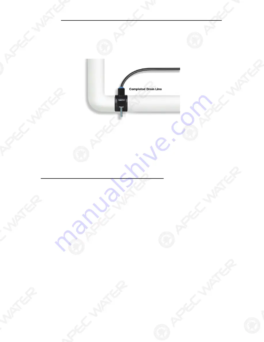
See Fig. 8, 8A.  Make sure to align the drain saddle hole to the drilled hole perfectly.


Mis-aligning these two holes will block the drain water and cause membrane damage.


Attach the drain saddle to the drain pipe and tighten the two screws evenly.

4.  Once the drain saddle is secured, push 1/4” black drain tubing into the Quick Connect fitting on the 

saddle. 

DO NOT

 use a “Insert” on the drain tubing. 

Fig. 8A

Step 3:   Drill A Hole For The RO Faucet

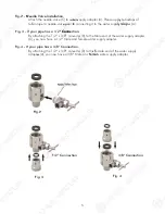
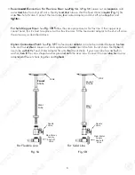
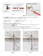
Drill 1/2” diameter hole for standard RO faucet.  

(Air-Gap faucet: drill 1”D hole.)

For best results use a 1/2” carbide-tipped masonry drill bit.

Wear safety glasses to protect your eyes while drilling the faucet hole.

Note:


  No need to drill a hole if an existing hole is available:

a)


Spare hole:

 If there is a spare hole in the sink covered by a chrome cover, simply remove the chrome 

cover and install the RO faucet there.

b

Spray hose: 

If the spray hose is not in use, remove the hose, and mount the RO faucet there. Remember 

to plug up the outlet under the main faucet. If the spray hose uses a diverter at the base of the spout, be sure 
to remove it to avoid trouble later on.

c

Hanging faucet: 

If drilling a hole is not feasible (i.e. rental home, drill tool not available etc.), the faucet 

can just hang on the cabinet door or wherever that is convenient. Be creative!

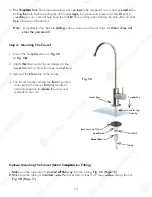
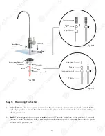
When drilling a hole for the RO faucet, choose a location that looks good, works well, and is most con-
venient for dispensing pure water. An ample flat area is required for the faucet base so that the faucet 
can be drawn down tightly.

1. 

Faucet location: 

Make sure the faucet stem will be accessible from below when the hole is drilled. 

If space is not available on the upper sink area, the faucet can be located on


the counter top by the 

edge of the sink. If the counter top is ceramic tile, the method for drilling the hole will be the same as 
for porcelain sinks.

2.


For Stainless Steel Sink:

 Before using a 1/2” carbide drill bit, an indent should be made with a 

center punch to keep the drill bit from walking. A small pilot hole will also aid the drill bit.

9

3.

See Fig

. 8,

8, 8

8A

A.  Make sure to align the drain

n

s

s

ad

ad

dl

dl

e hole to the drilled hole per

r

fe

fect

ct

ly

ly

.

.

g

p

y

Mis-a

li

lign

gnin

in

g these two holes will block the dra

a

in

in w

wat

at

er and cause membrane damage

ge

.

.

At

t

ta

tach

ch

t

the

h

 drain saddle to the drain pipe an

an

d

d

ti

tig

ghten the two screws evenly.

4.

4.


On

On

ce the drain saddle is secured, 

pu

push

sh

1

1

/4

/4

” black drain tubing into the Qu

ic

ic

k Co

Co

n

nnect fitting on the 

saddle.

DO NOT

 use a “Insert” on

n

t

t

he

he

d

dr

rain tubing. 

Fig. 8A

St

tep

ep 3

3

:   Drill A Hole For The RO Fa

Fauc

uc

et

et

Drill 1/2” diameter hole

e

f

for

or

s

standard RO faucet. 

(Air-Gap faucet: drill

ll

1

1”D

”D hole.)

For best results

u

use

se

a

a

1

1

/2

/

” carbide-tipped masonry drill bit.

Wear safety glasses to protect your eyes while drilling the faucet hole.

Note:

No need to drill a hole if an existing hole is

s

a

ava

vail

i

able:

g

a) Spare hole:

 If there is a spare hole in the sink co

o

ve

ve

re

re

d

d

by

by

 a chrome cover, simply remove the

he c

chr

hro

ome 

cover an

a

d install the RO faucet there.

b

b

)

)

Sp

Sp

ray hose: 

If the spray hose is not in us

s

e,

e, r

r

em

em

o

ove the hose, and mount the RO fau

auc

cet there. Remember 

to

o

p

p

lu

lu

g up the outlet under the main fauce

e

t.

t.

 If th

h

e spray hose uses a diverter at the ba

ba

se

se o

of 

th

th

e spout, be sure 

to

to remove it to avoid trouble later on.

c

)

Hanging faucet: 

If drilling a ho

ho

le

le

 is not feasible (i.e. rental home, drill to

o

ol

ol

n

n

ot

ot available etc.), the faucet 

can just hang on the cabinet doo

oor 

or

or wherever that is convenient. Be

c

cre

re

at

at

iv

iv

e!

e

When drilling a hole for

t

t

he

he

R

R

O

faucet, choose a location that looks

ks

g

g

oo

oo

d

d, works well, and is most con-

venient for dispensing pur

re

e

wa

wa

te

te

r. An ample flat area is required for the faucet base so that the faucet 

can be drawn down tightly.

1.

Faucet location: 

Make sure the faucet stem will be accessible from below when the hole is

is d

dri

rill

ll

e

ed. 

If space is not available on the upper sink area, the faucet can be located on the counte

ter

to

top

p b

by the 

edge of the sink. If the counter top is cerami

mi

c

c ti

tile

e

, the method for drilling the hole will be

be t

t

h

he same as 

fo

o

r po

porcelain sinks.

2.

2.

F

For

o

 Stainless Steel Sink:

 Before us

s

in

ng

g

a

a

1/2” carbide drill bit, an indent sh

h

ou

ould

ld b

be

e made with a 

center punch to keep the drill bit f

f

ro

rom

m walking. A small pilot hole will als

s

ai

ai

d

d

th

th

e drill bit.

Summary of Contents for Ultimate RO-QUICK90

Page 1: ...ON OWNER S MANUAL All Rights Reserved APEC Water Systems www FreeDrinkingWater com Ver 1 0 Models RO QUICK90 All Rights Reserv ved ed ed ed APE APE APE APEC Water Systems www FreeD D D Dr r rin nk k k...

Page 2: ......
Page 3: ...lease keep this O Ow wn ne er s Manual for future e r re ef fe erence It contains useful information on how to maintain and care for your APEC Reverse Osmosis water filter system TABLE OF CON NTE TENT...

Page 4: ...own the f fi in ne est t water filter in America Pl Plea e se read and become familiar r wi with th i ins structions and parts needed befor ore e pr pro oceeding with the i installation BEFORE INSTAL...

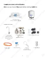
Page 5: ...for opening Membrane housing 1 Faucet Adapter 2 Com mp po on nents included with the RO O s sy ys st tem p p y M Ma ake sure you have all t th he es se e parts before starting in ns st ta al ll la ati...

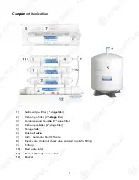
Page 6: ...10 Feed water inlet 11 Product filtered water outlet 12 Bracket 3 Com mp po on nent Itemization 1 Sediment pre filter 1st stage ge fil ilte t r 2 Carbon pre filter 2nd s sta tage ge f filter 3 Membran...

Page 7: ...THE SYSTEM Space Make sure there is sufficient s spa pace under the counter for installat tio ion n a an n area of about 14 L x 6 W x 6 5 H H f for or t the he system 11 D x 18 H for tank The RO syst...

Page 8: ...adapter Fig 2 Fig 3 Fig 4 1 2 Connection 3 8 Connection 5 Fig 2 2 N Needle Valve Installation Attach the needle valve C to w wat ater er s supply adapter A Please appl ply y 5 5 6 6 wr wraps of teflon...

Page 9: ...d d C Connection For Flex Line Riser S See ee Fi Fig g 5A Fig 5E Loosen nut and d se sepa para rate cold water ri rise ser r t tube from shut off valve Gently ben nd d ri rise ser r tube so that the F...

Page 10: ...ompression nut 7 Fig 5C 5 Needle Valve tubing connecti tion on i instructions Please first slide the met tal al c com ompr ression nut then the plastic sleeve and push the plastic insert all the way i...

Page 11: ...ortant DO NOT REMOVE the black drain tubing from the RO system system If you need to extend the drain tubing please use a union connector to connect additional length of tubing Note To avoid d p possi...

Page 12: ...fect ctly ly g p y Mis ali lign gnin ing these two holes will block the dra ain in w wat ater and cause membrane damage ge At tta tach ch t the h drain saddle to the drain pipe an and d ti tig ghten...

Page 13: ...er Lock Nut L k N t Fa Fauc ucet et Ad Adapter Tubing Coun nte ter r T Top p Counter Top Opening Fauc cet Base 3 For Porce cela lain in Sink Porcelain enameled sinks ca an n re read adily be chipped i...

Page 14: ...from the RO system without much pressure loss 11 Faucet cet Ba Bas se Black Loca ating Washer Lock Washer Lock Nut Insert Sleeve C Nut ompression N Counter Top Counte er T r Top op Ope Openin ning g T...

Page 15: ...H G A 12 IM MP PO OR RT TANT INSTALLATION N NO OT TICE Th The e Q Quick connect fittings come with a an n en e d plug that needs to be removed b bef efor ore e the tubing can be connected Please disc...

Page 16: ...age 7 13 Fig 11 Summary of Tubing Connections There are 4 connections See Fig 11 Fig 11A Point A to A X Co Conn nnect RO to COLD water supply Re Red d t tubing Point G to Y Y C Connect product water f...

Page 17: ...LINE 1 1st st S St tag age e Sediment pre r 2nd d S St tage Carbon pre r 3rd Stage Membrance and housing 4th Stage Carbon post lter DRA DRAIN IN WATER A A INP INPUT UT WATER A A DR DRINKI NKING NG WA...

Page 18: ...tubing from the RO to the Drai in n Sadd ddle le Fi itt ttin i g type Simply push the Clear tubing g i int nto the Quick Connect fitting N No o In Inse sert rts Sleeves or Nuts are needed to secure re...

Page 19: ...asily for filter replacement Fig 13A Fig 13B 16 Option p Mo Mout utin ing The RO System You c can a m mo ount the RO system on a side of cabi b ne net t or wall See Y Y Fig 13A This RO sy system m i i...

Page 20: ...hut O t O Valve Tee tting for icemaker output Bal Ba l Valve Position ON OFF Z H A Y X Insert Sleeve Tube Metal Nut Option p Ic ce e m ma aker Connection If you u w wan ant t to connect product water...

Page 21: ...s to fill When the tank is filled the R RO will shut off automatically 4 Drain Tank T T Please do not use the first tank k o of f w water Once the tank has filled d op open en p r r the drinking water...

Page 22: ...yst ste em requires very little maintenanc nce e Jus st t change the filter cartridges regul ular arly ly a as s suggested below Ke Keep ep t the system indoors away from ex xtr trem eme e he heat or...

Page 23: ...CTIONS How w To To R Re eplace Stages 1 2 Pre Filters Turn n O OFF FF cold water supply to RO system m Turn rn O OFF tank s ball valve Turn ON N th the e RO RO f faucet briefly to re reli liev eve e t...

Page 24: ...pply to RO system Turn O OFF FF t tan ank ball valve Lift up RO faucet lever r br brie iefl fly to T T relief the bui uilt lt u up p pressure inside the RO system Thi his s wi will ll make opening the...

Page 25: ...ge 33 22 Please read t th hi is s s se ection for useful RO system m a an nd d ma ai in nt tenance information TABLE OF CONTENT Part I RO O Ba B sics Ba Basi sic terms page 23 System flow diagram page...

Page 26: ...O O BASICS Th This is section provides basic concepts ts o on n ho h w w an RO system works how it per rfo form rms s in in relation to your ho house s water condition We hope e th this is i inf nform...

Page 27: ...has the most direc ect effe ect ct on how well y you ur r RO will perform With sufficient water er p pressure 85 psi max your RO s sys yste tem m wi ill function well gi give ve h hi igh output with h...

Page 28: ...re will dete erm rmi ine how full and how fast the storage ta ta k nk will be filled up Th The e st s ronger your input water pressure the e fa fast ster and fuller the tank can fill I If f wa wate te...

Page 29: ...um u p RO Systems The 3 3 mo most st common problems caused by low inp nput ut water pressure 1 Tank does not fill up ge et t li litt ttle le w wat ter from tank T T 2 Sluggish flow at the dispe pens...

Page 30: ...ewly I In ns st ta al lled RO System y y Af fte ter r in inst stal a lation if you encounter any of f th the pr prob obl lems described below please f fol ollo low w th this guide to trouble sh shoo o...

Page 31: ...uppl ply y is off W Turn on the water sup ppl ply y o or open Needle Valve turn needle ha hand ndle le coun nte er r cl clockwise T Tank s valve is closed T T Turn tank v val alve ve t to o an Open p...

Page 32: ...ter r le lea ak from any of the tubing connec ecti tion o s o on the reverse osmosis system Please review the steps be below w to to address the connection Please follow the st tep eps s be below Step...

Page 33: ...Re insert membrane correctly See Fig 14B Page 20 Water pressure too low causing TDS to be higher than an u usu sual W Raise water pressure or ad add d pump to RO O Input t so sour urce ce water has v...

Page 34: ...experiencing a leak from where the e ta tank ball valve attaches to the tank stem m you may not ha have ve applied enough Teflon tape to the ste em m h when you first installed the valve ve To To c c...

Page 35: ...m should shut off automatically y wh when the tank is filled When the RO fai ils ls t to shut off after ta tank k i is filled drain water will keep running do down w the drain depleting the pre f fil...

Page 36: ...try the he a abo bove procedure again another 2 3 3 tim mes es S Sometimes it takes several tries to get rid of all the air in t the he system If the noise persists af fte ter r a a fe few days that m...

Page 37: ...t In Inst stal allation Optional Ther re e ar are e 3 colored tubings on your Air Gap fa fau ucet At the end of each 1 4 tubi bing ng t the here is a Quick Con ne nect ct fi fitting The Quick Connect...

Page 38: ...l purchaser that for a per erio iod d of of one 1 year from the date of purchase the Product will be reasonably free of defects in materials and workmanship Within that one 1 year period from the orig...

Page 39: ...Product is not operated in compliance ce w wit ith h no normal municipal water conditions for which the pa part rtic icul ula ar model of this Product is intended 2 The person seeking to invoke the w...

Page 40: ...nical support contact us at Techsupport freedrinkingwater com 1 800 880 4808 Advanc ce ed d Purification Engineering Cor rp p 1320 S Johnson Drive City of Industry CA 91745 For questions o or r c co o...

Reviews: