Updated 6/16/2016
Copyright Apeks LLC, 2014
16
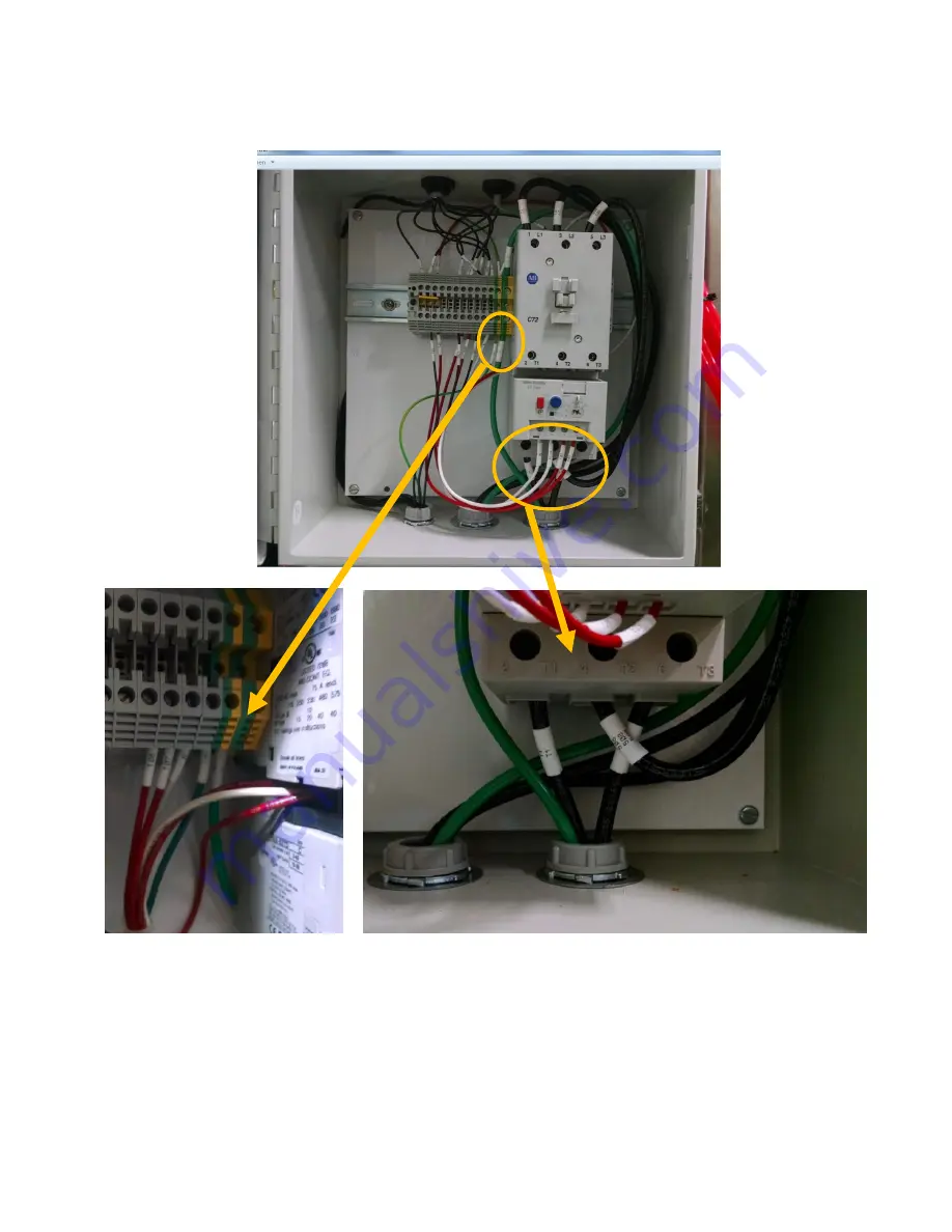
Electrical Connections between the Apeks system and diaphragm compressor
3.1.7.
Connect the diaphragm compressor electrical connections to the back of the Apeks
system as shown below by inserting labeled wire T1 to the bottom T1 of the motor
starter, T3 to T3, and ground wire to the ground terminal on the din rail immediately
to the left of the motor starter. NOTE: 3 Phase motors are wired differently.
Figure 17. Electrical connections from Diaphragm compressor to the Apeks system
3.1.8.
Wires for the pressure switches on the pump need to be wired in this panel as well.
3.1.8.1. Insert the conduit coming from the junction box on the pump into the receptacle
in the middle of the pump.
3.1.8.2. Terminate the wires in the bundle that are labeled into the terminal block
opposite of the wires with the same number. See figure below
Summary of Contents for 2000 PSI Series
Page 49: ...Updated 6 16 2016 Copyright Apeks LLC 2014 49 ...
Page 50: ...Updated 6 16 2016 Copyright Apeks LLC 2014 50 Appendix C CO2 Phase Diagram ...
Page 51: ...Updated 6 16 2016 Copyright Apeks LLC 2014 51 ...
Page 52: ...Updated 6 16 2016 Copyright Apeks LLC 2014 52 Appendix D Training Process ...


