Updated 6/16/2016
Copyright Apeks LLC, 2014
12
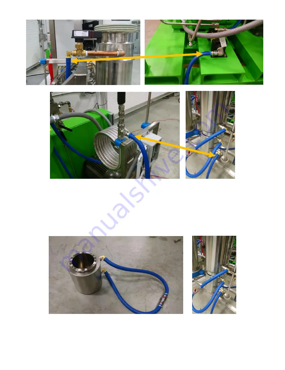
Figure 10. Location and orientation of coolant lines from the Apeks system to the diaphragm compressor.
3.1.5.
The separator side of the extraction system will be pre-assembled. In the event that
adjustments need to be made or the system gets taken apart during use, the water
flow path should always be from bottom to top in any vertically oriented vessel.
Figure 11. Image of 4 inch separator coolant lines.
Please note that these lines should not lay on any sharp
edges where abrasion can occur.
Summary of Contents for 2000 PSI Series
Page 49: ...Updated 6 16 2016 Copyright Apeks LLC 2014 49 ...
Page 50: ...Updated 6 16 2016 Copyright Apeks LLC 2014 50 Appendix C CO2 Phase Diagram ...
Page 51: ...Updated 6 16 2016 Copyright Apeks LLC 2014 51 ...
Page 52: ...Updated 6 16 2016 Copyright Apeks LLC 2014 52 Appendix D Training Process ...


