
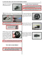


15
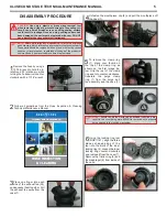
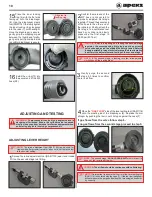
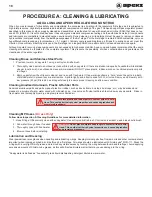
Place the inner locking
ring (4) with the flat side
facing up onto the diaphragm
(6). Use the diaphragm clamp
tool (RG911161) to slowly tighten
the inner locking ring clockwise
into the case (7) until handtight.
Once the diaphragm is secure,
gently grip the diaphragm pad
between the thumb and forefin
-
ger; gently pull from side to side
to confirm diaphragm is secure.
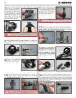
16
Install the o-ring (13) into
the swivel end of the MP
hose (28).
ADJUSTING LEVER HEIGHT
WARNING:
Compressed air can be highly explosive and is
dangerous if misused. Ensure the cylinder valve is opened
slowly. Use eye and ear personal protective equipment when
performing any tests involving compressed air.
CAUTION:
Prior to adjusting and testing the second stage
regulator, the accompanying first stage must be correctly
serviced and adjusted to a stable MP and fully tested. Refer to
the appropriate first stage technical manual before attempting
to perform the adjustment and testing of the second stage.
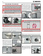
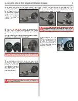
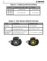
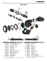
2
Confirm the male end of the
MP hose is connected to
a properly adjusted first stage
regulator. Thread the swivel end
of the hose to the other end of
the inline tool. Finally, attach the
first stage to a calibrated test
bench or cylinder and slowly
pressurize the first stage to
3,000 psi (207 bar).
1
Spread the inline adjustment tool (RA911123) apart and thread
it on the second stage inlet fitting.
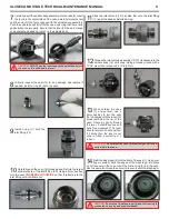
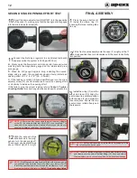
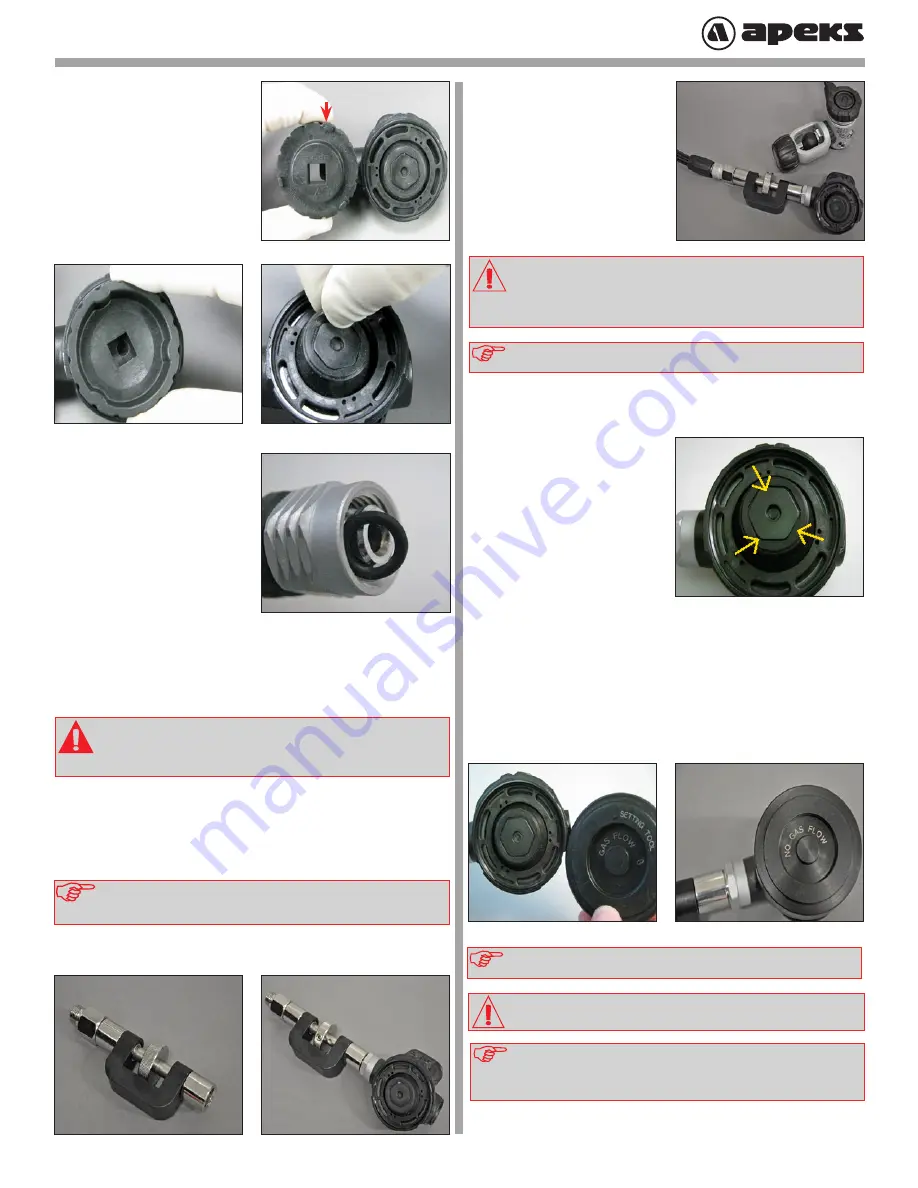
4
Place the
“GAS FLOW”
side of the lever setting tool (RA911116)
onto the plastic pad of the diaphragm (6). Depress the dia-
phragm by pushing the tool in until it stops against the case (7).
If gas flows from the valve follow step 6.
If no gas flows from the second stage proceed to step 5.
NOTE:
The second stage
“SHOULD LEAK AIR”
with this test. If it
does not, the lever is set too low.
NOTE:
It is important to ensure that the rim of the lever setting tool
(RA911116) is centered with the case (7). If the tool is misaligned it
will not measure the purge button (depth of pressing) and sensitiv-
ity, correctly.
3
Gently purge the second
stage 2-3 times to confirm
there is air flow.
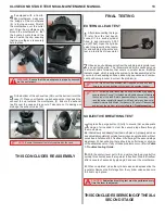
ADJUSTING AND TESTING
NOTE:
If The second stage is leaking, turn the inline adjuster
clockwise until the leaking stops.
CAUTION:
The air flow should be continuous with no fluttering.
NOTE:
The inline adjustment tool (RA911123) can be used for
crowns with a flat screwdriver slot or a hex hole. Set the inline tool
to the hex slot setting.
Align tool to
locking ring
10


