
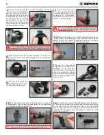


SECOND STAGE OPENING EFFORT TEST
10
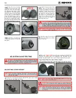
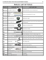
Insert the micro adjuster tool (RG911227) into the open side
of the case (7), making sure that the hexagonal bit engages
into the micro adjuster screw (23).
11
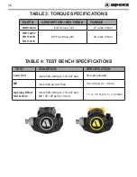
Connect the first stage regulator to a calibrated test bench
and pressurize the system to 3000 psi (207 bar).
a.
Slowly open the flowmeter control knob (start vacuum) while
watching both the magnahelic gauge and the intermediate pres-
sure gauge.
b.
When the MP gauge begins to drop, indicating the second-
stage valve is open, the magnahelic gauge should indicate an
opening effort of +1.4” to +1.6” (3.5 - 4.0mbar).
c.
If the reading is outside of these specifications, turn the micro
adjuster screw (15) counter-clockwise to lower the opening effort
or clockwise to increase the opening effort.
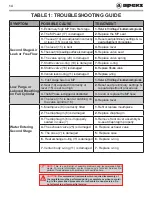
If this fails to give the correct reading refer to
Table 1: Trouble-
shooting Guide
for corrective guidelines and specific procedures.
NOTE:
A 2.5mm hex key can be used to adjust the micro adjuster
screw (15) if a micro adjuster tool (RG911227) is not available. The
open end of the case must be blanked off (place your thumb over
opening) to obtain a reading on the test bench.
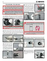
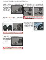
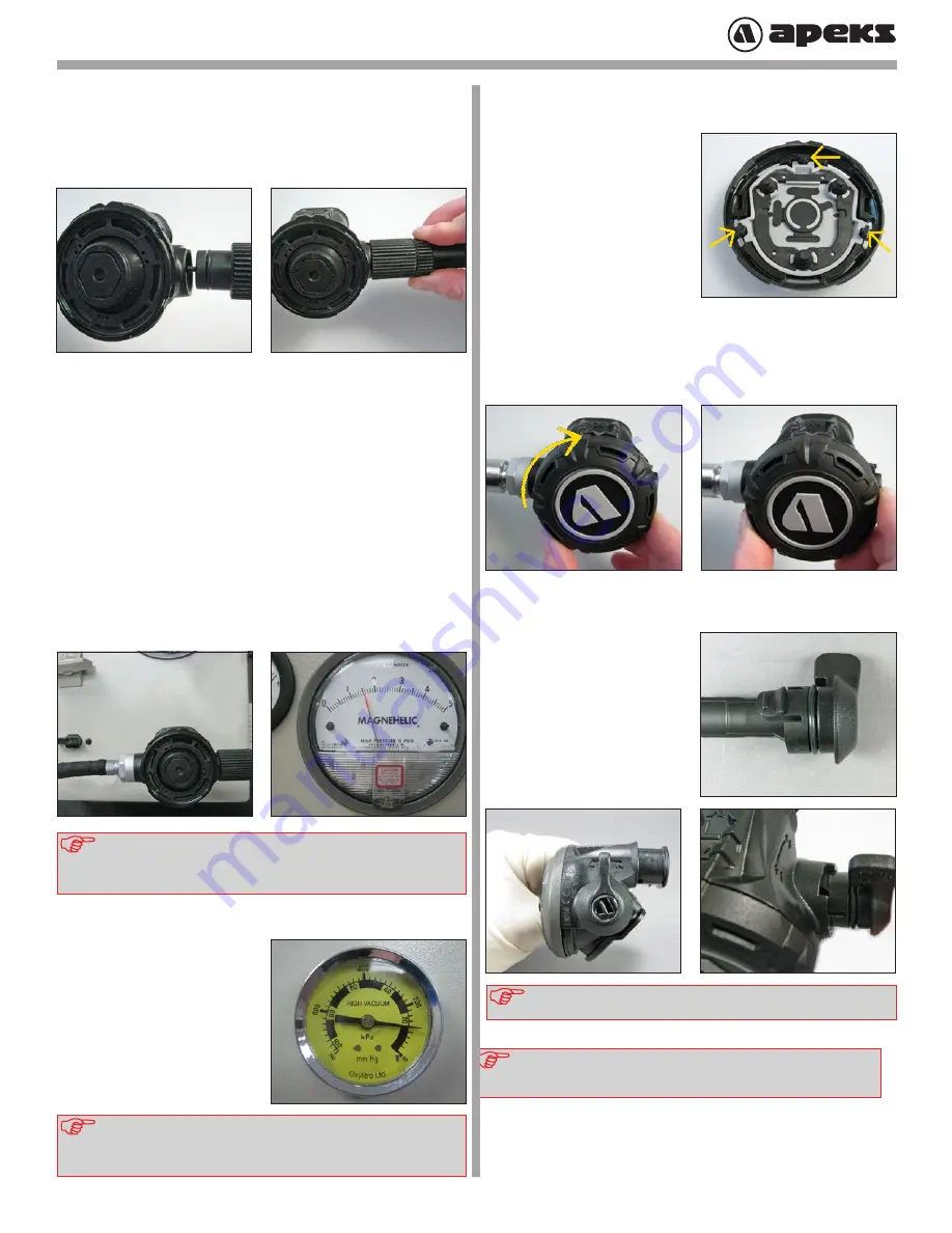
FINAL ASSEMBLY
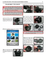
1
Place the purge button (2)
inside the clamp ring (1)
ensuring the three locating tabs
line up.
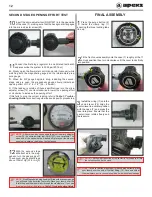
2
Fit the front cover assembly onto the case (7) roughly at the 11
o’clock position then turn clockwise until the cover locks firmly
into position.
3
Install the o-ring (11) onto the
venturi lever (24). Align the
venturi lever in a vertical position
with the case (7) and press the
lever into place. Ensure that the
venturi lever rotates freely and
feels secure.
NOTE:
The thumb grip section of the venturi lever needs to fit into
the cutout section on the case.
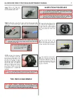
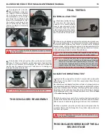
NOTE:
If the Magnehelic being used isn’t fitted with a vacuum gauge
you will need to perform the test orally. Place your thumb over the
inlet fitting and inhale normally through the mouthpiece. If you can
draw air in or hear air flow refer to,
Table 1:
Troubleshooting Guide.
NOTE:
To check that the diaphragm (6) has sealed correctly, place
your thumb over the end of the inlet fitting (10). Suck and hold at
the mouthpiece port, a vacuum should be held without any leakage.
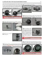
12
With the second stage
still attached to the mag-
nehelic, turn the gas supply off.
The vacuum gauge should read
above 100mm Hg (53.5 in-H
2
0)
12


