background image

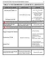
Cleaning Brass and Stainless Steel Parts

1.  Preclean in warm, soapy water* using a soft nylon bristle brush.

2.  Thoroughly clean parts in an ultrasonic cleaner filled with soapy water. If there are stubborn deposits, household white distilled    

     vinegar (acetic acid) in an ultrasonic cleaner will work well. DO NOT place plastic, rubber, silicone or anodized aluminum parts       

     in vinegar.
3.  Remove parts from the ultrasonic cleaner and rinse with fresh water. If tap water is extremely “hard,” place the parts in a bath         

     of distilled water to prevent any mineral residue.  Agitate lightly, and allow to soak for 5-10 minutes. Remove and blow dry with  

     low pressure (25 psi) filtered air, and inspect closely to ensure proper cleaning and like-new condition.

Cleaning Anodized Aluminum, Plastic & Rubber Parts

Anodized aluminum parts and parts made of plastic or rubber, such as box bottoms, box tops, dust caps, etc., may be soaked and 

cleaned in a solution of warm water mixed with mild dish soap.  Use only a soft nylon toothbrush to scrub away any deposits.   Rinse in 

fresh water and thoroughly blow dry, using low pressure filtered air.
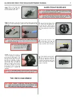
Cleaning MP Hoses


(Air use Only)

Follow Hose Inspection & Cleaning Guidelines for more detailed information

1.  

Hose fittings: Ultrasonically clean with soapy water; Use soft nylon bristle brush. If corrosion is evident, use a brass bristle brush.

2.  Run water through hose if needed
3.  Thoroughly rinse with fresh water
4.  Blow out hose before installing

Lubrication and Dressing

Wear powderless, latex gloves when handling and lubricating o-rings. Keeping internal parts free from skin oils and other contaminates is 

important when running enriched air nitrox through a first stage. All o-rings should be lubricated with Christo-Lube

®

 MCG-111. Dress the 

o-rings with a very light film of grease, and remove any visible excess by running the o-ring between thumb and forefinger.  Avoid applying 

excessive amounts of Christo-Lube grease, as this will attract particulate matter that may cause damage to the o-ring.

*Soapy water is defined as “household” grade liquid dishwashing detergent diluted in warm water.

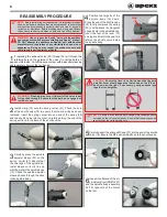
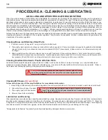
PROCEDURE A: CLEANING & LUBRICATING

AQUA LUNG AND APEKS REGULATORS AND NITROX

When it comes to issues of nitrox safety and compatibility, the concerns lie primarily with the regulator’s first stage as it is subjected to 

high inlet pressures. High inlet pressures lead to adiabatic compression or heating of the gas. The Aqua Lung or Apeks regulator product 

described in this manual, when properly cleaned and assembled, is authorized for use with enriched air nitrox (EAN) that does not ex-

ceed 40% (EAN 40). It is authorized because it has undergone adiabatic compression testing and the authorized service kit components 

and lubricants are compatible in elevated oxygen environments. During cleaning, a mild detergent must be used to remove condensed 

hydrocarbons (compressor oils) from the inside passageways of the first stage. For the first stage to remain EAN40 compatible, only use 

hyperfiltered compressed gas (hydrocarbons < 0.1 mg/m3). Ordinary compressed breathing air (Grade E) usually does not meet this 

criterion. Once ordinary breathing air is used, the first stage is no longer EAN40 compatible until it is cleaned and serviced again.

Although regulator second stage components are not exposed to high pressure EAN, Aqua Lung and Apeks recommend that the same 

cleaning procedures be followed for the complete regulator. This prevents the possibility of cross contamination and guarantees the 

cleanliness of the entire regulator. 

CAUTION:


Do not place plastic and rubber parts in contact with acid solu-

tions. This could alter their physical properties and cause degradation and 

premature breakdown.

CAUTION:


Do not place complete hose length in contact with acid solu-

tions. This could alter their physical properties and cause degradation 

and premature breakdown.

18

Summary of Contents for XL4 SECOND STAGE

Page 1: ...TECHNICALLY INSPIRED TECHNICAL MAINTENANCE MANUAL XL4 SECOND STAGE ...

Page 2: ...ION CHANGE MADE BY 15 20 03 22 19 Service Kit Part Number Change to RS135111 Aqua Lung America 15 03 22 19 AT75 Tool Part Number Change to RA911116 Aqua Lung America All 11 2020 All New Part Numbers Aqua Lung America CHANGE RECORD 2 ...

Page 3: ...TESTING 10 FINAL ASSEMBLY 12 FINAL TESTING 13 TABLE 1 TROUBLESHOOTING GUIDE 14 TABLE 2 LIST OF TOOLS 15 TABLE 3 TORQUE SPECIFICATIONS 16 TABLE 4 TEST BENCH SPECIFICATIONS 16 TABLE 5 RECOMMENDED LUBRICANTS CLEANERS 17 CLEANING AND LUBRICATION 18 MAINTENANCE NOTES 19 XL4 XL4 EXPLODED VIEW 20 CONTENTS 3 XL4 SECOND STAGE TECHNICAL MAINTENANCE MANUAL ...

Page 4: ... amount of use the product has received since it was manufactured or last serviced 6 When reassembling it is important to follow every torque specification prescribed in this manual using a calibrated torque wrench Most parts are made of either marine brass or plastic and can be perma nently damaged by undue stress 7 In order to make the product compatible with nitrox up to 40 O2 EAN40 the product...

Page 5: ... mechanism NOTE Before performing any disassembly refer to the exploded parts drawing which references all mandatory replacement parts These parts should be replaced with new and must not be reused under any circumstances regardless of the age of the product or how much use it has received since it was last serviced CAUTION Use only a plastic or brass o ring removal tool when removing o rings to p...

Page 6: ...he o ring 11 underneath the inlet shroud 12 Align tool cutout venturi tab CAUTION Take care when handling the seat 14 The seal ing surface of the seat must be protected from damage or the regulator will leak 11Insert a 5mm hex key into the reg hose threaded end of the inlet fitting 10 and turn the seat 14 CLOCKWISE Carefully push the seat out the other end of the inlet fitting 13Insert the long en...

Page 7: ...NOTE The following parts should be checked for cracks deep scratches excessive wear and tear and distortion Sealing faces grooves and bores should be checked for scratches INSPECTION PROCEDURE NOTE Before performing any reassembly procedures there are several parts that must be inspected The following section details the parts and areas that must be checked 1Inspect the back face of the front cove...

Page 8: ...ing carrier into one end of the spring 20 and the shuttle valve into the other carefully guiding the end of the spring carrier into the bore of the shuttle valve 3Carefully place the spindle adjuster sleeve 22 on the spring carrier 21 Ensure that the two legs of the spindle ad juster sleeve correctly line up with the slots in the spindle body 16 Check the spindle adjuster sleeve passes through the...

Page 9: ...et shroud 12 hex side first onto the inlet fitting 10 past the already installed o ring 12Thread the inlet shroud assembly 10 12 clockwise into the spindle body 16 until snug Using a torque wrench with a 13 16 crow foot torque to 2 2 ft lb 3 Nm 13While holding the case 7 at eye level use a 5mm hex key to turn the seat 14 clockwise until the lever 15 drops just below the rim of the case Check by ge...

Page 10: ...ose to the other end of the inline tool Finally attach the first stage to a calibrated test bench or cylinder and slowly pressurize the first stage to 3 000 psi 207 bar 1Spread the inline adjustment tool RA911123 apart and thread it on the second stage inlet fitting 4Place the GAS FLOW side of the lever setting tool RA911116 onto the plastic pad of the diaphragm 6 Depress the dia phragm by pushing...

Page 11: ...el until the inline tool engages the seat 14 Turn the seat counter clockwise by approximately 1 16 of a turn This will raise the lever 15 Continue to adjust in 1 16 turns until there is a steady flow of air 8Turn off the air supply and purge the second stage by pressing the center pad of the diaphragm 6 Pull back on the adjust ment wheel of the inline tool and remove it from the second stage Remov...

Page 12: ...st be blanked off place your thumb over opening to obtain a reading on the test bench FINAL ASSEMBLY 1Place the purge button 2 inside the clamp ring 1 ensuring the three locating tabs line up 2Fit the front cover assembly onto the case 7 roughly at the 11 o clock position then turn clockwise until the cover locks firmly into position 3Install the o ring 11 onto the venturi lever 24 Align the ventu...

Page 13: ...eeply from the mouthpiece A properly serviced and adjusted regulator should deliver air upon deep inhalation without excessive inhalation effort freeflow or fluttering of the second stage diaphragm When exhaling there should be no fluttering or sticking of the exhalation valve If any of these problems occur refer to Table 1 Troubleshooting Guide b With the venturi lever set to the position tap the...

Page 14: ...lace valve seat 6 The valve spring 20 is damaged 6 Replace valve spring 7 Shuttle valve o ring 19 is damaged 7 Replace o ring 8 Shuttle valve 18 is damaged 8 Replace Shutle valve 9 Venturi lever o ring 11 is damaged 9 Replace o ring Low Purge or Labored Breathing on Full Cylinder 1 First stage has low MP 1 RefertoFirstStageTroubleshootingGuide 2 Seat 14 adjusted incorrectly or lever 15 is set too ...

Page 15: ... A 11 16 13 16 Wrench Disassembly and assembly N A 2 5mm 5mm Hex Key Removal installation of seat 14 Micro adjuster 23 N A Torque Wrench Apply torque to parts listed in Table 3 Torque Specifications N A 11 16 13 16 Crow Foot Apply torque to parts listed in Table 3 Torque Specifications N A Side Cutters Trim exhaust valve N A Magnifier with Illumination Sealing surface inspection N A Ultrasonic Cle...

Page 16: ... 12 27 in lbs 3 Nm RH114257 RH114119 RH113115 MP Flex Hose 28 45 in lbs 5 Nm TEST CONDITION SPECIFICATION Leak Test Inlet 2500 3000 psi 172 207 bar No leaks allowed MP Inlet 3000 psi 207 bar 130 145 psi 9 10 bar Opening Effort Std Octo Inlet 2500 3000 psi 172 207 bar MP 130 145 psi 9 10 bar 1 4 1 6 H2 0 3 5 4 0 mbar 16 ...

Page 17: ...NT PRIEST cedex JOHN LAWSON DIST SCOTSHAW BROOK HOUSE BRANCH ROAD LOWER DARWEN LANCASHIRE BB3 0PR Liquid Dishwashing Detergent diluted with warm water Degreaser for brass and stain less steel parts general cleaning solution for plastic and rubber Household grade TABLE 5 RECOMMENDED CLEANERS LUBRICANTS CAUTION Silicone rubber requires no lubrication or preservative treatment DO NOT apply grease or ...

Page 18: ...ng the o ring between thumb and forefinger Avoid applying excessive amounts of Christo Lube grease as this will attract particulate matter that may cause damage to the o ring Soapy water is defined as household grade liquid dishwashing detergent diluted in warm water PROCEDURE A CLEANING LUBRICATING AQUA LUNG AND APEKS REGULATORS AND NITROX When it comes to issues of nitrox safety and compatibilit...

Page 19: ...MAINTENANCE NOTES 19 XL4 SECOND STAGE TECHNICAL MAINTENANCE MANUAL ...

Page 20: ...uthpiece Clamp XL4 Grey RG911254 Mouthpiece Clamp Black 9 RG911123 Mouthpiece XL4 Grey RA117137 Mouthpiece Black RG912456 Mouthpiece Yellow 10 RG912343 Inlet Fitting Shrouded 11 RG912225 O ring 10 pk 12 RG912344 Inlet Shroud 13 RG912222 O ring 10 pk 14 RG912237 Seat 15 RG912281 Lever 16 RG912163 Spindle Body 17 RG912198 MP Seat Silicone 18 RG912112 Shuttle Valve 19 RG912235 O ring 10 pk 20 RG91208...

Page 21: ...TECHNICALLY INSPIRED Rev 11 2020 Aqua Lung USA 2340 Cousteau Court Vista CA 92081 760 597 5000 www aqualung com XL4 AUTHORIZED TECHNICIAN TECHNICAL MAINTENANCE MANUAL XL4 SECOND STAGE ...

Reviews: