

WARNINGS, CAUTIONS, & NOTES
Pay special attention to information provided in warnings, cautions and notes
that are accompanied by one of these symbols:
WARNINGS
indicate a procedure or situation that may result in
serious injury or death if instructions are not followed correctly.
CAUTIONS
indicate any situation or technique that will result
in potential damage to the product, or render the product
unsafe if instructions are not followed correctly.
NOTES
are used to emphasize important points, tips and reminders.
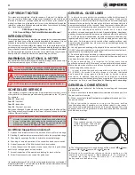
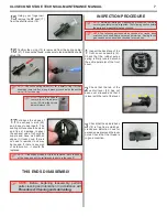
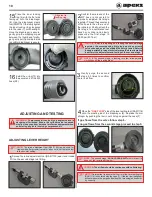
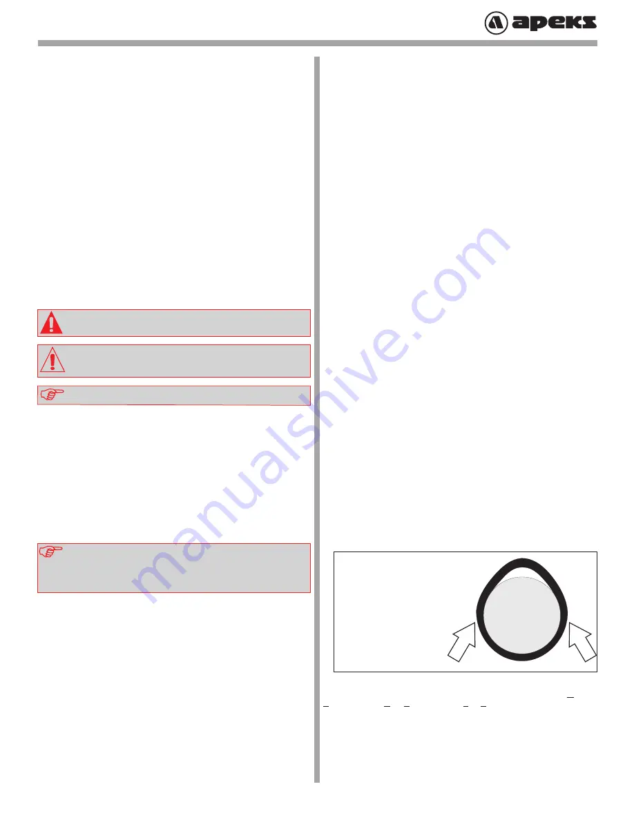
Pinch Method
Press upwards on sides of o-ring to
create a protrusion. Grab o-ring or
insert o-ring tool at protrusion.
COPYRIGHT NOTICE
This manual is copyrighted, all rights reserved. It may not, in whole or in
part, be copied, photocopied, reproduced, translated or reduced to any
electronic medium or machine-readable form without prior consent in
writing from Aqua Lung International. It may not be distributed through the
internet or computer bulletin board systems without prior consent in writing
from Aqua Lung International.
©2020 Aqua Lung America, Inc.
XL4 Second Stage Technical Maintenance Manual
INTRODUCTION
This manual provides factory prescribed procedures for the correct service and
repair of the Aqua Lung or Apeks products described in this manual. It is not
intended to be used as an instructional manual for untrained personnel.
The procedures outlined within this manual are to be performed only by
personnel who have received Factory Authorized training through an Aqua
Lung or Apeks Service & Repair Seminar. If you do not completely understand
all of the procedures outlined in this manual, contact Aqua Lung to speak
directly with a Technical Advisor before proceeding any further.
GENERAL GUIDELINES
1.
In order to correctly perform the procedures outlined in this manual, it
is important to follow each step exactly in the order given. Read over the
entire manual to become familiar with all procedures before attempting to
disassemble the product in this manual, and to learn which specialty tools
and replacement parts will be required. Keep the manual open beside you
for reference while performing each procedure. Do not rely on memory.
2.
All service and repair should be carried out in a work area
specifically set up and equipped for the task. Adequate lighting, cleanliness,
and easy access to all required tools are essential for an efficient repair facility.
3.
As the product is disassembled, reusable components should be seg-
regated and not allowed to intermix with nonreusable parts or parts from
other units. Delicate parts, which contain critical sealing surfaces, must
be protected and isolated from other parts to prevent damage during the
cleaning procedure.
4.
Use only genuine Aqua Lung or Apeks parts for the service of this product.
DO NOT attempt to substitute an original part with another manufacturer’s,
regardless of any similarity in shape or size.
5.
Do not attempt to reuse mandatory replacement parts under any circum-
stances, regardless of the amount of use the product has received since it
was manufactured or last serviced.
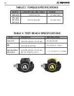
6.
When reassembling, it is important to follow every torque
specification prescribed in this manual, using a calibrated torque wrench.
Most parts are made of either marine brass or plastic, and can be perma-
nently damaged by undue stress.
7.
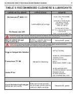
In order to make the product compatible with nitrox up to 40%
O2 (EAN40), the product must be properly cleaned, lubricated
and assembled using genuine Aqua Lung or Apeks replace-
ment parts. In addition, assembly must be carried out in a clean
environment using powderless, latex gloves or equivalent. For more detailed
information, be sure to read
Procedure A: Cleaning and Lubricating.
GENERAL CONVENTIONS
Unless otherwise instructed, the following terminology and techniques
are assumed:
1.
When instructed to
remove
,
unscrew
, or
loosen
a threaded part, turn
the part counter-clockwise.
2.
When instructed to
install
,
screw in,
or
tighten
a threaded part, turn
the part clockwise.
3.
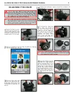
When instructed to
remove
an o-ring, use the pinch method
(see illustration below) if possible, or use a brass or plastic o-ring removal
tool. Avoid using hardened steel picks, as they may damage the o-ring
sealing surface. All o-rings that are removed are discarded and replaced
with brand new o-rings.
4.
The following acronyms are used throughout the manual:
MP
is Medium
Pressure;
HP
is High Pressure;
LP
is Low Pressure.
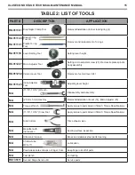
5.
Numbers in parentheses reference the key numbers on the
exploded par ts schematics.
For example
, in the statement,
“...remove the o-ring (7) from the crown (8)...”, the number 7 is
the key number to the crown o-ring.
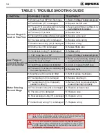
If a regulator fails item #1,2,3 or 4, the entire regulator should be overhauled. If
a regulator fails #5,6,7 or 8, it will be up to the technician’s discretion whether
or not a full overhaul is required.
NOTE:
A unit that receives heavy or frequent use, such as rental, in-
struction, or commercial applications, should be serviced at least twice
a year - or more often - depending on the conditions of use and the
manner in which it is maintained. (Refer to the care and maintenance
procedures outlined in the Regulator Owner’s Manual.)
An Official Inspection consists of:
1.
A pressurized immersion test of the entire unit to check for air leakage.
2.
Checking for stable medium pressure that is within the acceptable range.
3.
Checking for opening effort that is within the acceptable range.
4.
Checking for smooth operation of the control knob and venturi switch.
5.
A visual inspection of the filter for debris or discoloration.
6.
A visual inspection of the exhaust valve to see that it is in good shape
and that it’s resting against a clean surface.
7.
A visual inspection of the mouthpiece looking for tears or holes.
8.
Follow Hose Inspection document for guidelines.
SCHEDULED SERVICE
If the regulator is in good working order, it is permissible to overhaul it every
other year with an inspection procedure being performed on the “off” years.
For example:
Year #1
: Inspection
Year #2
: Overhaul
Year #3
: Inspection
Year #4
: Overhaul, and so on.
Both Inspections and Overhauls need to be documented in the Annual Ser-
vice & Inspection Record located in the Owner’s Manual to keep the Limited
Lifetime Warranty in effect.
4


