

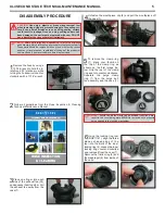
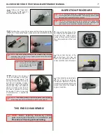


WARNING:
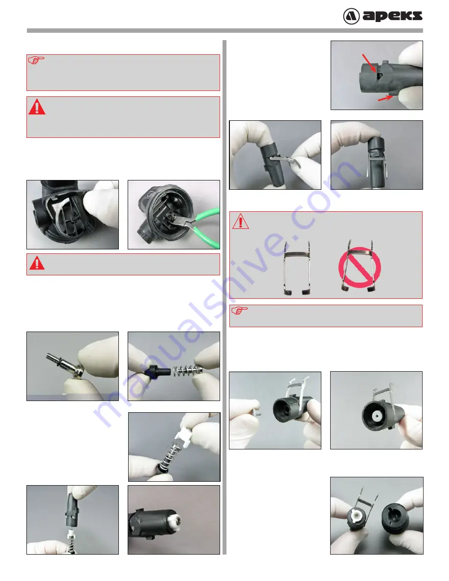
Flooding may occur if the tail of the valve is not
fully pulled through. Ensure that the barb has engaged on
inside of case.
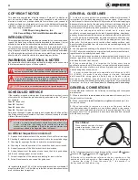
REASSEMBLY PROCEDURE
NOTE:
Before performing any reassembly, it is important to inspect
all parts, both new and those that are being reused, to ensure that
every part and component is perfectly clean and free of any dust,
corrosion, or blemishes. Before dressing each o-ring with Christo-
Lube
®
, check to ensure it is clean, supple, and free of any blemish.
WARNING:
Use only genuine Apek's
®
parts, sub-assemblies,
and components whenever assembling any Apek's
®
product.
DO NOT attempt to substitute an Apek's
®
part with another
manufacturer’s, regardless of any similarity in shape, size or
appearance. Doing so may render the product unsafe, and
could result in serious injury or death.
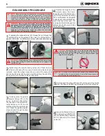
1
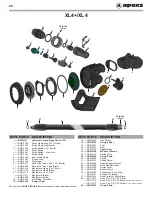
If replacing the exhaust valve (25) thread the tail through the
retaining hole on the outside of the case (7) until the barb en-
gages on the inside. Cut off the excess stem with side cutters leaving
approximately 5mm of the tail behind.
2
Install o-ring (19) onto the spring carrier (21). Check the bore
of the shuttle valve (18) to ensure that the old o-ring has been
removed. Insert the spring carrier into one end of the spring (20)
and the shuttle valve into the other, carefully guiding the end of the
spring carrier into the bore of the shuttle valve.
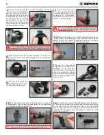
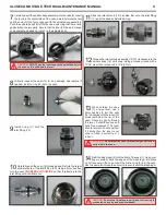
3
Carefully place the spindle
adjuster sleeve (22) on the
spring carrier (21). Ensure that
the two legs of the spindle ad-
juster sleeve correctly line up
with the slots in the spindle body
(16). Check the spindle adjuster
sleeve passes through the slots
in the spindle body.
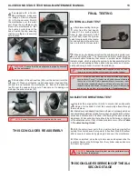
NOTE
:
Ensure that the lever has a full range of movement and does
not catch on the valve spindle body. Ensure that the spring can be
seen through the valve spindle hole.
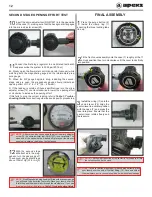
CAUTION:
Ensure that lever is not twisted and that legs are
parallel. Lever should appear as that shown on the left, not
as shown on the right. If necessary, gently squeeze legs
together to straighten.
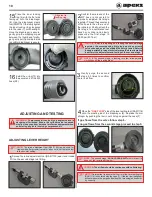
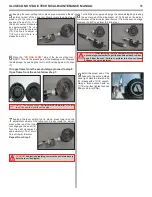
5
Carefully insert the silicone MP seat (17) into the end of the shuttle
valve (18). Ensure the MP seat is sitting flush to the shuttle valve.
6
Inspect the flat end of the mi
-
cro adjuster tool (RG911227)
and the spindle body assembly
(14-22), take note of the cutout
on the tool.
4
Position the large fin of the
spindle body (16) down.
Press the end of the shuttle valve
(18) to fully compress the spring
(20), until it passes the triangular
shaped hole in the spindle body.
Insert the feet of the lever (15)
one leg at a time into the gap, this
retains the shuttle valve inside
the spindle body.
Large Fin
Gap
8


