APEN GROUP SPA reserves the right to make changes deemed to be required to its products or documentation
AH-New
condensing air handling unit
36
code HG0310.05GB ed.A-2010
AH
37
code HG0310.05GB ed.A-2010
AH
HG0131.00 A 002
HG0310.00_IM 0012
10m
CARTIGLIO cod. X07003 ed.0411
-
MODIFICA APPROVATA DA
-
APPROVATO DA
-
-
-
-
-
-
DATA MODIFICA
MODIFICA DISEGNATA DA
-
DESCRIZIONE MODIFICA
ESP
-
-
DATA
DISEGNATO DA
Rame
MATERIALE
SCALA
®
ApenGroup
Heating and Conditioning Solutions
ESP
DISEGNO
DESCRIZIONE
1:3
Quote senza indicazione di
tolleranza:
Classe di Tolleranza
ISO 2768 - M
DISEGNO DI PROPRIETA' APEN GROUP spa E' VIETATA LA RIPRODUZIONE E LA DIFFUSIONE ANCHE PARZIALE SENZA L'AUTORIZZAZIONE DELL'APEN GROUP spa
ISO 2768 - C
per lavorazioni in tranciatura
PESO G
FOGLIO
3212.57
A3
5.7.
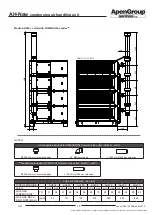
GAS Connection
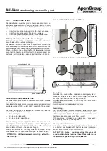
Use the gas line connections only with CE certified components.
AH modules are supplied complete with:
•
dual gas valve;
•
stabiliser and gas filter.
Al components are fitted inside the burner housing.
To complete the installation, as required by the current
regulations, the following components must be fitted:
•
anti-vibration joint;
•
gas valve;
•
gas filter.
NOTE: AN
EN126 certified gas filter with filtration level
lower than or equal to 50 microns must be used, with no
pressure stabiliser, with great capacity, since the filter
supplied as standard, upstream of the gas valve, has a
limited surface.
IMPORTANT: For proper maintenance, connect the AH
module by means of a seal and swivel gasket.
Avoid using threaded connections directly on the gas connection.
Current legislation allows a maximum pressure inside the rooms,
or thermal stations, of 40 mbar; higher pressure values must
be reduced before entering the boiler room or the site where
the AH module is installed.
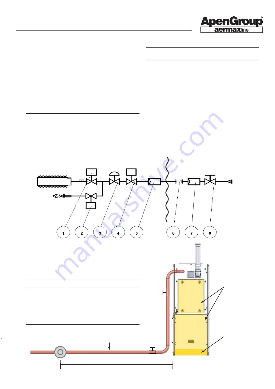
KEY
1
Main burner gas solenoid valve
2
Pilot burner gas solenoid valve
3
Pressure stabiliser
4
Safety gas solenoid valve
5
Gas filter (small section)
------------------------------------------------------------------
6
Anti-vibration joint
7
Gas filter (large section)
8
Gas valve
During the installation, we recommend tightening the
external gas supply pipe nut without exceeding the
tightening torques shown below:
- Ø 3/4'':
150 Nm;
- Ø 1'':
200 Nm;
- Ø 1 1/2'':
300 Nm.
It is strictly prohibited to supply gas to the circuit with
pressure higher than 60 mbar. Such pressures could
cause the valve to break. If pressure is higher than 60mbar,
a pressure reducer must be installed at a distance of
at least 10 m and no pressure stabiliser must be fitted
between the pressure reducer and the unit, but leaving
the gas filter.
To be provided by the installer
Included with the PCH module
Max 60 mbar
Do not position the gas
duct in front of removable
panels or components to
be serviced.
Panel
REMOVABLE
Panel
REMOVABLE
Pressure
reducer
Air intake filter
section


