AH-New
condensing air handling unit
APEN GROUP SPA reserves the right to make changes deemed to be required to its products or documentation
38
code HG0310.05GB ed.A-2010
AH
39
code HG0310.05GB ed.A-2010
AH
2
3
H
G
0150_
C
3_010
1
HG0150_C3_011
HG0150_C3_005
5.8.
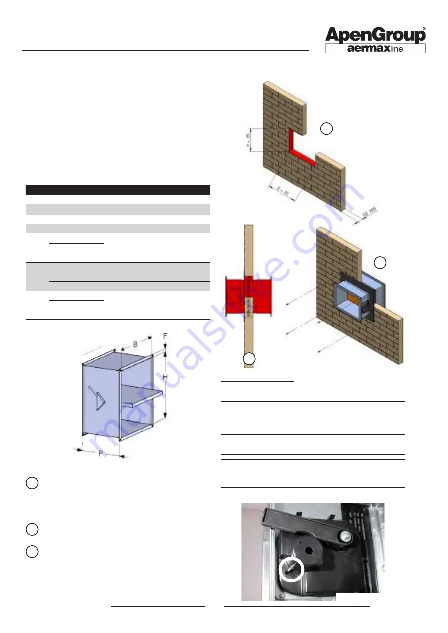
Fire damper installation
The fire damper is available as optional equipment, both at intake
and delivery. Fire dampers consist of a galvanised iron sheet
frame, the compartmentalisation and sealing blade and the blade
closing device. All dampers have the following specifications:
•
reaction to fire EI120S
•
thermal cut-out with fuse set on 72°C;
•
microswitch, IP55, supplied as a standard and installed
on damper
•
supplied dampers are certified.
Fire damper kit
Model
Code
B
H
P
F
shutter
[mm] [mm] [mm] [mm]
AH034
Delivery and Intake
G23646
800
450
510
35
AH045
Delivery and Intake
G23666
1100
450
510
35
AH105
Delivery and Intake
G23686
1500
450
510
35
AH160
AH210
Delivery
G23726
1000
970
510
35
Horizontal Intake
Vertical Intake
G23756
1200
650
510
35
AH320
Delivery
G23736
1200
1170
510
35
Horizontal Intake
Vertical Intake
G23766
1670
800
510
35
AH420
Delivery
G23746
1400
1370
510
35
Horizontal Intake
Vertical Intake
G23776
1670
800
510
35
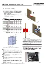
USE OF FIRE DAMPER
To activate the damper rotate the control lever counter-clockwise.
To release the damper press the button highlighted in the figure.
IMPORTANT: Pay attention to the direction of rotation of the
lever: in case of vigorous rotation in the wrong direction the
closing device may break.
IMPORTANT: After installation, check that there are no
obstacles for the correct blade rotation.
IMPORTANT: When the AHU is disconnected from
the structure, close or protect ductworks to prevent
atmospheric elements from entering.
INSTALLATION OF FIRE DAMPER ON RIGID WALL
1
Prepare in the wall an opening with both base and height
increased by 85 mm with respect to the nominal dimensions
of the damper; for walls made of concrete blocks or bricks it
is recommended to provide a strengthening beam above the
opening;
2
Insert the damper in the opening so that the fixing flange
rests on the wall surface;
3
Fasten the damper to the wall through the holes present
in the fixing flange using self-tapping screws or screw anchors
with 6 mm diameter.
For further information, refer to the manual supplied with
the dampers.


