APEN GROUP SPA reserves the right to make changes deemed to be required to its products or documentation
AH-New
condensing air handling unit
42
code HG0310.05GB ed.A-2010
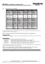
AH
43
code HG0310.05GB ed.A-2010
AH
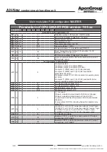
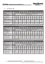
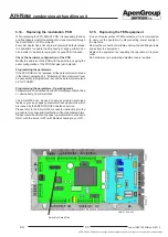
Parameters of CPU-SMART PCB version 7.03.xx
PARAMETER
AH034
AH065
AH105
AH160
AH210
AH320
AH420
DESCRIPTION
Control parameters
d0
(2)
-
5
Flame modulation: 2=NTC1; 5=0÷10Vdc; 7=Modbus (SmartWeb
in PID mode)
d1
(2)
-
5
Type of equipment: 0=heater; 2=boiler; 5=PCH; 8=PKA/E;
10=Queen; 12=Fan heater
d2
(2)
-
0
Remote lockout signal output (Q1): 0=disabled; 1=enabled
d3
(2) sec
5
Fan delay time ON (RL2): 0÷255
d4
(2) sec
10
Fan delay time OFF (RL2): 0÷255 (1=5sec. 60=300 sec.)
d5
(2)
-
0
Flue gas T control enabling (NTC3): 0=disabled; 1=enabled
NOT USED
d6
(2) sec
5
Interval between switching off and on (Off timer): 0÷255
d7
(2)
-
0
1= Fault reset counter; 2= Burner hour-meter reset
d8
(2)
-
0
Boiler antifreeze enabling (NTC1): 0=disabled; 1=enabled
NOT USED
d9
(2)
-
0
Dampers enabling: 0=disabled; Do Not Change
d10 (2)
-
0
Continuous ventilation: 0= disabled; 1= enabled (fans always
active); 2= enabled with delay par.d3 upon remote heat request
- active in Fault in case of heat request
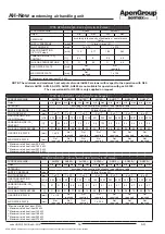
Burner parameters
b1
(2) rpm
210
182
195
172
195
195
195
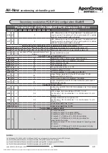
Motor RPM MINIMUM value (PWM1): 90÷999 (1=10 RPM)
b2
(2) rpm
710
651
635
655
635
635
635
Motor RPM MAXIMUM value (PWM1): 90÷999 (1=10 RPM)
b3
(2) rpm
300
340
240
355
240
240
240
Motor RPM START-UP value (PWM1): 90÷999 (1=10 RPM)
b4
(2)
-
2
HALL signal divider: 2÷3
b5
(2) rpm
50
Error F3x; no. of revolutions x10 (50=500rpm): 0÷300
b6
(2) sec
20
Error F3x; error dwell time before fault F3x: 0÷255
b7
(2) sec
30
Pre-cleaning time with maximum output: 0÷255. DO NOT
CHANGE THE PRESET VALUE.
b8
(2) sec
10
Flame stabilisation time (ignition): 0÷255
b9
(2) sec
10
Combustion chamber post-cleaning time (FAN ON): 0÷255
b10 (2)
%
5
Motor rpm % increase for each b11 seconds: 1÷100
b11 (2) sec
1
Time interval for motor rpm increase: 1÷100
b12 (2)
%
30
Antifreeze mode FAN motor modulation % value: 30÷100
b13 (2)
pwm
65
Integral factor value (ki_pwm) for PWM1 calculation: 0÷249
b14 (2) pwm
45
Proportional factor value (kp_pwm) for PWM1 calculation:
0÷249
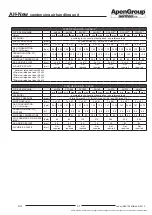
b15 (2) sec
0
0
0
(*)
(*)
(*)
(*) with d1=0 or 5: delay time ON flame control equipment (TER);
with d1=2 (boiler): F85/F86 water flow delay alarm at start-up
Secondary modulation PCB (PCH) configuration:
SLAVE
NOTES:
(*) Please refer to table of "Parameter b15 for multiple module machines” here below


