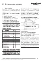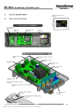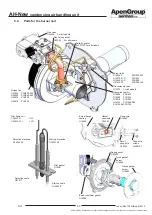
AH-New
condensing air handling unit
APEN GROUP SPA reserves the right to make changes deemed to be required to its products or documentation
44
code HG0310.05GB ed.A-2010
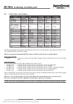
AH
45
code HG0310.05GB ed.A-2010
AH
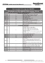
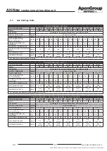
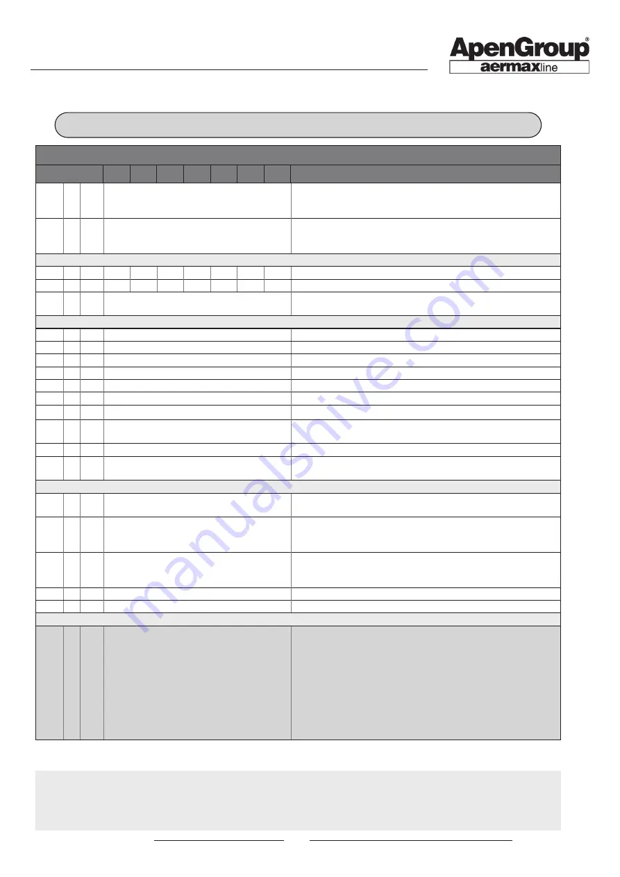
Parameters of CPU-SMART PCB version 7.03.xx
PARAMETER
AH034
AH065
AH105
AH160
AH210
AH320
AH420
DESCRIPTION
b16 (2)
-
0
ID5 - Blower fan control: 0=input disabled; 1=enabled with N.C.
input required; 2=enabled with N.O. input required; 3= enabled
with N.C. input required with auto-reset;
b17 (2)
-
3
ID6 - Blower fan control: 0=input disabled; 1=enabled with N.C.
input required; 2=enabled with N.O. input required; 3= enabled
with N.C. input required with auto-reset;
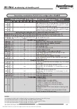
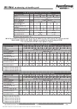
Heat input and fuel instantaneous consumption calculation parameters
(a)(b)(c)(d)
Qmin (3) kW
7.6
12.4 21.0 16.4 21.0 21.0 21.0
Minimum heat input (ref. Lower calorific value - Hi)
Qmax (3) kW 34.85 65.0 99.9 82.0 99.9 99.9 99.9
Maximum heat input (ref. Lower calorific value - Hi)
LCV (3)
kW/m
3
see table of "Gas-type parameters” here
below
Lower calorific value (Hi)
Limit NTC1 control (with D0=5 or 7)
SEL (2)
-
3
Modulation probe 1=NTC probe1; 3=NTC3 probe
S1
(2)
-
0
NTC1 probe enabling: 0=disabled; 1=enabled
ST1 (1)
°C
75
NTC1 setpoint: -10÷140
SP1 (2)
°C
5
SP1 hysteresis: 0÷10
XD1 (3)
%
20
Proportional band from 4 to 100
TN1 (3) sec
100
Integral coefficient: 1÷255
AC1 (3)
-
1
0=only modulation; 1= modulation and ON/OFF
TH1 (2)
°C
85
Upper Temperature limit for fault F51 activation: 10÷95
autoreset if NTC1<TH1-15°C
S3
(2)
-
1
NTC3 probe enabling: 0=disabled; 1=enabled
TH3 (2)
°C
85
Upper temperature limit for F53 fault activation (auto-reset if
NTC3<TH3): 0÷140
Control 0/10 Vdc - D0=5
H51 (1)
-
1
Active only with D0=5 (0/10V) 0=modulation only; 1=modulation
and ON/OFF
H52 (1)
V
0.5
OFF voltage, burner switching off if H51=1: 0÷10
1st. Module = 0.5; 2nd. Module = 1.5; 3rd. Module = 2.5; 4th.
Module = 3.5.
H53 (1)
V
0.5
Voltage Delta with burner ignition ON
1st. Module = 0.5; 2nd. Module = 1.0; 3rd. Module = 1.5; 4th.
Module = 1.5.
H54 (3) sec
10
Lower input dwell time: 0÷255
H55 (3) sec
10
Upper input dwell time: 0÷255
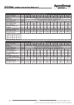
Fan and damper output control
H11 (2)
-
0
0=output disabled;
1=analogue output Y1 enabled (PWM);
2=analogue output Y2 enabled (0÷10Vdc);
3=outputs Y1 (PWM) and Y2 (0÷10Vdc) enabled;
4=outputs Y1 (PWM) and Y2 (0÷10Vdc) enabled for
pressostatic structures;
5=analogue output Y2 (0÷10Vdc) enabled for operating mode
d1=10/12;
6=outputs Y1 (PWM) and Y2 (0÷10Vdc) enabled for boiler
summer ventilation with EC fan heater
Secondary modulation PCB (PCH) configuration:
SLAVE
NOTES:
(a)
Models AH105, AH160, AH210, AH320 and AH420 are not approved for operation with gas G2.350 (Poland)
(b) For AH065 model, set Qmax = 57 (kW) for operation with gas G2.350 and G27 (Poland)
(c)
For AH105 model, set Qmax = 94 (kW) for operation with gas G25.1 (Hungary) and G27 (Poland)
(d)
For AH160 model, set Qmax = 75 (kW) for operation with gas G27 (Poland)


