APEN GROUP SPA reserves the right to make changes deemed to be required to its products or documentation
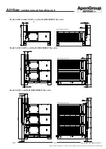
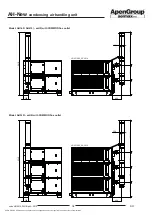
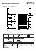
AH-New
condensing air handling unit
44
code HG0310.05GB ed.A-2010
AH
45
code HG0310.05GB ed.A-2010
AH
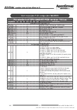
Parameters of CPU-SMART PCB version 7.03.xx
PARAMETER
AH034
AH065
AH105
AH160
AH210
AH320
AH420
DESCRIPTION
H12 (1)
V
4
Y2 output minimum voltage: 0÷10
H13 (1)
V
10
Y2 output maximum voltage: 0÷10
H14 (3)
%
80
PWM minimum value: 0÷100
H15 (3)
%
100
PWM maximum value: 0÷100
H16 (3)
-
2
0, 1=not used;
2=blower modulation proportional to FAN (do not change);
3=blower modulation proportional to B1 input (0-10V);
4 proportional to B2 input for pressure check in pressostatic
structures;
5= proportional NTC1 for checking Queen/Fan heaters (only
output Y2)
H17 (3)
-
1
0=PWM (Y1) or 0/10V (Y2) output according to "direct" logic;
1=PWM (Y1) or 0/10V (Y2) output according to "reverse" logic;
2= PWM (Y1) "reverse" and 0/10V (Y2) "direct” output;
3= PWM (Y1) "direct" and 0/10V (Y2) "reverse” output
H18 (1)
-
8
Y2 output fixed voltage
H19 (3)
-
32
Reading of NTC1 to which the minimum value of Y2 output
corresponds - NOT USED
H20 (3)
-
65
Reading of NTC1 to which the maximum value of Y2 output
corresponds - NOT USED
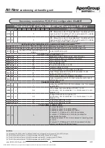
Table of "Parameter b15 for multiple module machines”
PARAMETER
SLAVE 1
SLAVE2
SLAVE 3
SLAVE 4
DESCRIPTION
b15
(2) sec
0
10
20
30
with d1=0 or 5: delay time ON flame control equipment (TER);
with d1=2 (boiler): F85/F86 water flow delay alarm at start-up
Table of "Gas-type parameters"
PARAMETER
G20
G25
G25.3
G25.1
G27
G2.350 G30 G31
DESCRIPTION
LCV (3)
kW/m
3
9.45 8.13 8.31 8.14 7.75 6.75 12.4
Lower calorific value (Hi)
Secondary modulation PCB (PCH) configuration:
SLAVE


